VCCS with constant Zin
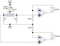
Original VCCS has variable Zin, it reaches lowest Zin in the middle of the wipe and higher when moving away from middle.
Hopefully this design would work to get constant Zin.
Adjust CCS for Zin range, with 0.1ma, the current over LDR is around 0.02-1ma, so for SR2 it's aournd 5-7K, for SR3 around 20-30K.
Maximus, any comment? I think 0.1ma should be fine for DS1802 and 1ma output fine for OPAMP direct drive.
Attachments
Lightspeed remote control
Hi Folks,
I am running behind schedule with business commitments because I had to take time off this last month to refurbish my workshop and computer systems to cope with the increased demand for power supply products. I had reached the point where there was not enough workspace and storage space to deal with all the business requirements. I have several consultancy contracts in operation at present that are requiring a lot of attention and I am afraid these consultancy obligations are not helping the situation.
Please accept my apologies for the delay in answering your questions. I will be very busy this week catching up with outstanding orders for PHD so it will be Saturday before I can look at any questions on the Lightspeed remote control.
For those looking for boards and modules I will continue to make them available as long as interest continues.
Regards
Paul
VCCS with constant Zin
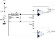
Diagram in #2262 is wrong, should use Volt ref instead of CCS, current range over LDR is 0.03-3ma.
The idea is to keep current over DS1802 wiper lower than 1ma, and use OPAMP to get 3X current output.
Say R is the resistance between W and L of DS1802, the current over LDR shunt is in ratio of 0.6V/(R+680) and over LDR serial is in ratio of 0.6V/(45000-R+680). Expect in certain range resistance/current over LDR is linear, so Zin should be in the ratio of (R+680)/0.6+(45000-R+680)/0.6 which is a constant value.
Any better idea to get a 0.6V or lower volt reference?
Attachments
Passive Preamp forum
Time to do some more recruiting for our own Passive Preamp forum/heading, please vote here.
http://www.diyaudio.com/request/
Cheers George
Time to do some more recruiting for our own Passive Preamp forum/heading, please vote here.
http://www.diyaudio.com/request/
Cheers George
Re: VCCS with constant Zin
Have you tried this?
Here are my naive comments.
I get approx a 1.5V drop over the LED. I dont know how .6V would get the LED to flicker. Maybe though I havent tried it.
.03mA may be to high. I get them to work with .00001A and less but I cant measure lower. Anyway, sure it would work but you might not get as much resistance as you could. I have an odd batch of LDRs that are reacting to extremely low current and this is not the norm but my last batches were tested with .000125A which was only at 40k in series with the voltage.
What if you switched it around a bit and ran the current output of the opamps into the DS1802 instead of through the DS1802 first? You could get high and extremely low current.
Also, you get lowest distortion with 2.5V over the LED. Thats somewhere on the Silonex website. Distortion is low anyway though.
Just comments let me know if I am full of it.
Uriah
2A3SET said:Diagram in #2262 is wrong, should use Volt ref instead of CCS, current range over LDR is 0.03-3ma.
The idea is to keep current over DS1802 wiper lower than 1ma, and use OPAMP to get 3X current output.
Say R is the resistance between W and L of DS1802, the current over LDR shunt is in ratio of 0.6V/(R+680) and over LDR serial is in ratio of 0.6V/(45000-R+680). Expect in certain range resistance/current over LDR is linear, so Zin should be in the ratio of (R+680)/0.6+(45000-R+680)/0.6 which is a constant value.
Any better idea to get a 0.6V or lower volt reference?
Have you tried this?
Here are my naive comments.
I get approx a 1.5V drop over the LED. I dont know how .6V would get the LED to flicker. Maybe though I havent tried it.
.03mA may be to high. I get them to work with .00001A and less but I cant measure lower. Anyway, sure it would work but you might not get as much resistance as you could. I have an odd batch of LDRs that are reacting to extremely low current and this is not the norm but my last batches were tested with .000125A which was only at 40k in series with the voltage.
What if you switched it around a bit and ran the current output of the opamps into the DS1802 instead of through the DS1802 first? You could get high and extremely low current.
Also, you get lowest distortion with 2.5V over the LED. Thats somewhere on the Silonex website. Distortion is low anyway though.
Just comments let me know if I am full of it.
Uriah
VCCS with constant Zin
0.6V is to make current over DS1802 less than 1ma (maximum according to datasheet), the OPAMP control the current over LDR (amplify 3x times) by adjust the voltage over LDR, I am gonna use 0.03ma-3ma to get 20K pot with 40-50db.
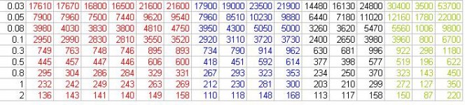
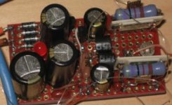
By the way, I just got 3 pair match perfectly and another 2 pair matched in 10% from 16 SR3.
I am using CCS to test the LDR, with LM334 and 10K variable resistor.
0.6V is to make current over DS1802 less than 1ma (maximum according to datasheet), the OPAMP control the current over LDR (amplify 3x times) by adjust the voltage over LDR, I am gonna use 0.03ma-3ma to get 20K pot with 40-50db.
By the way, I just got 3 pair match perfectly and another 2 pair matched in 10% from 16 SR3.
I am using CCS to test the LDR, with LM334 and 10K variable resistor.
Attachments
Two of your pairs would be great, one of them would not make it into my pairs, but I am super picky and that is a great percentage out of 16. Well, if I wast testing out of 16 I would definitely take them all ") Awesome percentages. I have to build an LM334 circuit when I get home. On vacation right now.
Awesome percentages. I have to build an LM334 circuit when I get home. On vacation right now.
So are you testing one at a time or how many?
I have to build one with SR3 to hear the sound. I wonder if its the same resistive material as the SR2.
Uriah
Awesome percentages. I have to build an LM334 circuit when I get home. On vacation right now.So are you testing one at a time or how many?
I have to build one with SR3 to hear the sound. I wonder if its the same resistive material as the SR2.
Uriah
Combine VCCS and CCS version
I was testing 4 pairs at each time with 15V supply, 1K resistor in series to monitor the current (only get one DMM), should test 16 together as it's a pain. Have to pick up close pair from excel chart, then match together again as even 0.001ma can make pretty big difference.
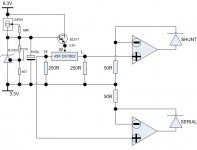
Here is another diagram I am thinking, the 250R can be lowered to make the adjustment range bigger, with 250R it's around 44DB, with 680R it's 37DB. Adjust the 1K pot for Zin.
I am going to build the CCS version first then this one as it's more complicate. I like the DS1802 balance control so I can use those 10% pair (1db difference?) as well.
I was testing 4 pairs at each time with 15V supply, 1K resistor in series to monitor the current (only get one DMM), should test 16 together as it's a pain. Have to pick up close pair from excel chart, then match together again as even 0.001ma can make pretty big difference.
Here is another diagram I am thinking, the 250R can be lowered to make the adjustment range bigger, with 250R it's around 44DB, with 680R it's 37DB. Adjust the 1K pot for Zin.
I am going to build the CCS version first then this one as it's more complicate. I like the DS1802 balance control so I can use those 10% pair (1db difference?) as well.
Attachments
Lightspeed remote control
Hi Dave G, post 2260,
1. The VCCS and IR boards are still available.
2. I have provided circuit diagrams and board layouts for the ‘Lightspeed’ remote control. This is enough information for a reasonably experienced constructor to copy my application of a single ended, IR remote controlled/chassis push button controlled, LDR volume control using either MKI or MKII ‘lightspeed’ LDR configuration based on George’s passive volume control. I am too busy at present to write out an application note for every option that is possible with the VCCS module. Alternative application configurations can be discussed on the forum thread.
3. The easiest and cheapest solution for balanced operation retaining the left/right balance control function is to wire a second set of LDRs for the anti-phase signals with their LEDs wired in series with the single ended set. You will need to have reasonably well matched quads for the series LDRs and the Shunt LDRs to do this successfully. To ensure enough headroom for the op-amps to drive the series connected LEDs you will also have to raise the voltage of the 3v3 TL431 shunt reg in bias chain to 5 volts and change the 12 volt 3 terminal power supply regulator for a 15 volt reg (it may even need to be slightly higher depending on the LED forward voltage) with a corresponding increase to the raw supply voltage to ensure the 15 volt reg does not drop out of regulation.
4. You will probably need to select different LDR types to achieve 25K.
Sorry no time for any more right now. I will try to get some time on the thread tomorrow.
Regards
Paul
Infra Red transmitter battery voltage
Hi Kent,
The recommended operating range of the supply voltage of the HT12A is 2v4 to 5 v with an absolute maximum of 6v.
I chose to use NiMH rechargeable batteries in my remote and these have a cell voltage of 1v2 and are supplied in packs of four which gives a nominal supply voltage of 4v8.
I like to fit a polarity protection diode with battery driven equipment as sooner or later acidental reverse polarity will occur which could zap the chip. The diode I use for this function has a forward voltage of around 0v7 and I wanted to ensure that I hade reasonable headroom above the minimum 2v4 operating voltage of the HT12A. Allowing for the this and the fact that some would fit AA or AAA cells I fitted 2 polarity protection diodes in series to prevent the 6v maximum voltage of the HT12A being exceeded when using four fresh AA cells.
In practice 3 x AA cells will work fine and you can replace one of the polarity protection diodes with a wire link to extend the useful life of the cells a little by allowing more headroom towards the end of the battery life.
Regards
Paul
Lightspeed remote control
Hi Folks,
Those who decide to use the ‘Lightspeed’ MK1 version (seriesR/shunt LDR) should fit an LED in the position of the unused series LDR LED connection. These LEDs are connected to terminals 11/12 and terminals 13/14. This will define the load for the series voltage controlled current sources and prevent stability problems. Make sure that you get the LED polarity correct.
Hi 2A3SET,
I am a little too busy to get into expanding multiple variations on a theme at present. The VCCS works fine as it is in my system so I have little incentive to fiddle with it. I am afraid there are just too many other projects that I have to give priority to at the moment. I am happy to discuss applications of the VCCS and IR boards but I will leave the modifications to others with more time. Keep publishing your results. I am sure there are others who are interested in ‘Lightspeed’ control system development. The LDRs are just so damn good for volume control sonically. It’s a shame they are so tricky to use.
By the way the current through the DS1802 pot in the VCCS application is around 0.11ma. This is well within the Dallas/Maxim data sheet specification.
Hi Udaily,
Current would still flow through the LDR LED with low voltage operation of the DS1802, as the current is provided via the main 12 volt supply via the op-amp output stages, which would settle at whatever voltage the LED needs to conduct the current defined by the potential across the current setting resistors. However. I am not sure how the DS1802 potentiometer section would behave with such a low voltage across it.
Regards
Paul
Lightspeed Remote Control
Hi Folks,
I am starting to get some feedback from users of the VCCS and IR remote control.
The balance control appears to be fine enough to correct any audible channel imbalance caused by mismatched LDRs. This backs up my findings with the original prototype VCCS module where I did no matching at all. However I still recommend using LDR pairs matched at three points in their response curve. The response curves should then be reasonably similar and this will remove the need to adjust balance every time you change volume if you were to use unmatched LDRs with different response curves.
When mounting the Infra-Red Receiver behind a preamp front panel, make sure that the hole you drill to allow the IR light to activate the IR receiver chip is of reasonable size. This will allow a wider window of remote control operation in the listening area.
Regards
Paul
TX2575 is the best
TX2575 is very transparent, TF020 is almost close (a little bit sweet, musical?), so so for Shinkoh, maybe because of I have too many Shinkohs (total 6) in my AMP as gate-stopper.
The impedence is stable with CCS and matched pair.
By the way, the difference between regualar POT and LDR is huge when listening with speaker (Lowther DX3), while not that big with headphone (HD600), both are driven by same AVVT 2A3 amplifier.
Lightspeed remote control
Hi K.K.,
I designed the Lightspeed remote control using the Holtek chips so remote controls for other equipment could not interact with the LDR volume control accidentally.
I am not sure if the holtek IR chip remote codes are supported by the harmony universal remote. I would suggest you ask their tech dept.
Regards
Paul
- Home
- Source & Line
- Analog Line Level
- Lightspeed Attenuator a new passive preamp