john65b said:Anyway, I did not know this was a LDR base pre. So this and the Hafler Iris are LDR based? Are there any more commercial pres out there that have the LDR based volume control?
Just my first MkI versions going back some 30 years. then came the>
Hafler 80's (Cyber-Optic),
http://www.stereophile.com/solidpreamps/689hafler/
Melos late 90's
http://www.stereophile.com/headphones/796melos/index.html
And yes of course the Dartzeel NHB-18NS early 07 $25,000usd http://www.6moons.com/audioreviews/dartzeel2/preamp.html
Part of the Herve Deletraz interview on the Dartzeel
Q: What is wrong with conventional volume controls?
A: You lose something. I use a system that varies resistance with light. However, until all the patents are in place, I would prefer not to specify the details.
Of course the patents were stopped quick smart
Your buddy John, with the Melos that you fixed, it's the top one called the SHA-Gold-Reference 3 box list on this was around $20K
10 years ago, nearly all of them were returned with the LDR's going out of calibration, then Melos folded, they used to call the Lightspeed control system the Porzilli Photopot and it was Mark Porzilli that ulitized it late 90's.
Cheers George
If James's way doesn't register.
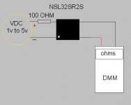
Use a multimeter and write down the 5 resistance readings of the LDR's at the 5 different vdc 1, 2, 3, 4 & 5 volts.
The resistance readings should be within 10% for all 4 LDR's at each of the 5 voltage settings, this is the simplest way.
Then you'll have 4 matched LDR's
Wait 1 min warm up for each reading
Cheers George
Attachments
Hi everybody,
I finally did the job ! I found 2 groups very close from each other with resistances ranging from 35 to 110 ohms for 2 to 5 Volts. The third group had a larger dispersion (from 20 ohms for the lowest value to 140 ohms for the highest) and some mismatches in the range...
A couple of months ago, George sent me a schematics for a balanced stereo attenuator which included 1k-0% variable resistances for each wire. What can I do to improve the usable range ? Finally, with 10 k input impedance for my amplified monitors, the use of a buffer seems to be necessary isn't ?...
Thank you all for your help !")
I finally did the job ! I found 2 groups very close from each other with resistances ranging from 35 to 110 ohms for 2 to 5 Volts. The third group had a larger dispersion (from 20 ohms for the lowest value to 140 ohms for the highest) and some mismatches in the range...
A couple of months ago, George sent me a schematics for a balanced stereo attenuator which included 1k-0% variable resistances for each wire. What can I do to improve the usable range ? Finally, with 10 k input impedance for my amplified monitors, the use of a buffer seems to be necessary isn't ?...
Thank you all for your help !
Hi Pierre,
it has been a while since we heard from any of the guys doing uC control of the LDRs - maybe during the winter over there...
Broadly speaking, there were only 3 systems - all different, naturally!
1. Barry (BarryBlue) based a current control design around the AD420 (posts 994, 1013) -
2. Thomas (Tolu) mentioned the ACT1655 with a 16bit voltage control system and 1 dac per LDR (posts 1448,1510, 12)
3. The "audiofandante" project has been developing on Italian website - not sure about progress but quite ambitious.
Paul Hynes (Maximus) developed a remote volume control (posts 1217 ...1511) around the CD1802 - not exactly uC, but a rather neat design. Pcbs are available, maybe kits, too.
Tom Gootee did a lot of sim work and also included VCCS info in post 1184.
Perhaps we may see a Lightspeed device built into your developing Comp -> Dac interface system, or perhaps added to the dac o/p stage?
Your website articles, and designs, are very interesting.
Hi-
I've been intrigued by this thread! Thanks to the people that have summed it up- made reading thru it much easier.
I have just completed the Salas RIAA JFET preamp on another thread and would like to add this to it's output.
Maximus's solution looks very good for the remote operation (any boards available?).
I am looking at other cheap-o solutions for remote control, as well. What about just getting a motorized dual pot and add a vellman IR relay kit?
http://www.vellemanusa.com/us/enu/product/view/?id=500341
It would be nice to add balance control, too.
Thanks!
-Kent
For you guys looking for remote control you have a lot of Internet suppliers here are 2 reliable links I order from :
http://www.analogmetric.com/store/goods.php?id=769
http://cgi.ebay.co.uk/Preamplifier-...photoQQcmdZViewItemQQ_trksidZp1742.m153.l1262
Hope this helps !
OndesX
http://www.analogmetric.com/store/goods.php?id=769
http://cgi.ebay.co.uk/Preamplifier-...photoQQcmdZViewItemQQ_trksidZp1742.m153.l1262
Hope this helps !
OndesX
Hi folks,
There are a few boards left. I piggy-backed a set of boards on one of my pre-production trial sheets which I use to verify a number of board layouts all at once. I usually order 10 sheets for beta testing before committing to production board runs. Five sets of the pre-production boards are already committed leaving five available for those wishing to try this remote control system. The pre-production boards are fully functional but they need tidying up, before any production run, as I have made a couple of simple changes to ease usage.
The VCCS (voltage controlled current source) board is the most important part of the set as this is the business end that controls the LDRs. It has two 5 pin headers on the board allowing the use of push button switches on a preamp chassis and/or an infra-red control system. Both types of control are active at the same time in an either/or manner. The VCCS board is unique but there are a number of options regarding the infra-red control system. These are available from a variety of sources. For instance, Rapid Electronics (www.rapidonline.co.uk) do a 4 bit infra red remote control kit using pre-programmed PIC chips (order code 70-0200) for less than £15. The transmitter would need a hand held box for the remote unit. This is the kit I adapted for my system. I made new boards as this was a more convenient fit in my system but the kit can be readily adapted for the job. Also Rentron offer the “firestick” kit, using Holteck chips, and although I have not tried this kit, I see no reason why it could not be adapted.
Some of you on the forum are suggesting the use of remote controlled potentiometers to control the “Lightspeed”. This is feasible although to include balance control is likely to increase costs beyond the cost of a VCCS solution, as two motor driven potentiometers are required together with additional drive circuitry. Remember that potentiometers also wear out and the tolerance between the pots is usually quite wide. The VCCS design has balance control built into it’s functionality. Some are suggesting using DACs to provide the LDR control often requiring circuitry that needs programming which is beyond most DIY enthusiast’s abilities. The VCCS circuit has been designed to offer all the required functions of a remote controlled stereo volume/balance control, using LDRs, offering precision and simplicity at low cost.
As a service to Lightspeed enthusiasts I am prepared to initiate a production run of the VCCS boards and offer the VCCS as a built and tested module if enough interest is shown. At least 20 firm orders are required to make this financially viable. Anyone interested in the board or the module should e-mail me at paul@paulhynesdesign.com and I will place you on the list. Once I have twenty firmly interested persons on the list I will initiate the board order. Those who have e-mailed me since I first posted about this remote control project, who are still interested, should e-mail again to confirm their interest. Please accept my apologies because I am too busy to go through the thousands of e-mails that I have received over the last year to find you.
To give an idea of cost I would expect to offer the PCB for the VCCS for less than £12 and the built and tested VCCS module for less than £60. An application note will be included in this price. Carriage costs will vary depending on where you live.
As low cost infra-red kits that are easily adaptable to interface with the VCCS module are available, I feel that it would not be financially viable to offer an alternative for these. I am not prepared to offer component kits for this project so do not ask. It will either be the board or the module.
Please note that the LDRs will not be supplied with the VCCS module. This is not designed to compete with George’s Lightspeed but to enable remote control conversion of Lightspeed for those who wish to do so, or for members of the DIY fraternity to set up their own “Lightspeed”. The VCCS module will also run the series resistor and shunt LDR configuration for those who wish to use this.
George has generously enabled this possibility by releasing information about the circuit he developed. Without him you would still be living in the dark ages as far as musical transparency is concerned. Throughout life each individual has opportunities to offer the world something of merit. Most don’t bother. I don’t know what else you have done during your life George but this is a good one.
Regards
Paul
Hi George,
You don't owe me anything, but if you insist, mine's a pint. I will collect if I ever get to Australia.
Nowadays I fall over without a drink.
I don't know the origin of "fell walking" but it was used a lot in Cumbria where I used to live and "fell" just means hill or small mountain as far as I am aware.
Regards
Paul
Hi Paul,
Good to hear from you, and that things have settled down a bit.
I just went back over your design again and it really is a neat bit of work. [Cct = post #1387, on page 56]
Those remote control pots don't appear that expensive at first glance (AM = 28gbp and the other ones a bit more) but this is only the pot, so the complete unit (w/out the LDRs) for about twice that (Oz$120) ready built and tested is actually a pretty good deal.
I can't resist this, Paul! - please add my name to your list.
Hi JH,
Thanks. You are number two on the list, 18 to go for a board run.
The current design is slightly simpler due to adoption of range setting based on Nelson Pass's findings. High current drive is no longer required for the LEDs so the opamp buffer trannies are no longer in the circuit. There is still some spare current drive for those that want a little more drive to their LEDs.
Regards
Paul
Yes, the strange pre-occupation with really wide vol ranges for diy use, is a bit of a mystery - I seldom use anything near half the range of the "normal" vol control.
One question about reducing the current - this would change the operating impedance values of the LDRs, yes? And would this change the units I/P and O/P impedance much?
Also, is it possible to add an o/p buffer (like a k170,j74) with external +/- supply? It'd be really useful if you could fit it in.
Curiously, I never did try the idea of adding a high value parallel resistor across the LDR's resistance for a more linear "high" setting (low diode current).
Did anybody else try this in practice?
Hi jh,
I agree regarding volume control range, though having small steps through the range is useful.
Reducing the maximum current through the LEDs does shift the operating impedance but it is not a severe change. I am driving the gate capacitance of an IXYS IXTH 20N50D directly from the LDR’s in my system without noticeable loss of the audible highs.
Check out Nelson’s tables for the various resistance levels at a selection of operating currents to get an idea of the range. The four current setting resistors in the VCCSs can be chosen to set the current scale where you want, to suit your system. In theory the LF347 quad opamp that I use can supply up to 20ma per opamp and only two will be any where near full drive at any on time.
You could certainly fit a buffer circuit after the Lightspeed circuit. I am reluctant to add bits to the VCCS board as it will add to the cost. The whole idea of this was to find an easy to apply low cost modular solution for constructors. Also I do not wish to infringe Nelson Pass's copyright by adding his suggested complementary buffer to the board.
I haven’t tried adding a parallel resistor across the LDRs as I am happy with the performance in my system.
Regards
Paul
- Home
- Source & Line
- Analog Line Level
- Lightspeed Attenuator a new passive preamp