georgehifi said:Just wanted to make sure, now how can we get rid of your 1vdc of dc offset without a coupling cap, what opamp are you using on the output of the cd? what I/V stage? and what da convertor? Post a diagram if you have one.
Hi George,
yes - getting rid of my dc offset & coupling cap would be great.
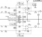
Here is the circuit diagram - it is just as show except the o/p cap is replaced with a 20 ohm resistor & the 22K resistors are removed.
The DAC has voltage o/p
cheers
mike
That BA5460 dual opamp COULD be the source of your 1vdc of offset, can you get a data sheet on this? I had a quick look but it's going to take a bit more than that, you may have to pay for it. If it is the source of your 1vdc of offset, it MAY simply be fixed by changing it for a good fet input opamp such as, my favourite AD825 (they are smd single and need Brown Dog adapter boards) or another favourite if you like a tubish sound OP275 they are dual 8 pin dil and cheap, first get the data sheet on the BA5460.
Cheers George
Cheers George
This could very well be the source of the dc offest, most of it anyway, it has has bipolar input transitors, I would first chage it out for a OP275 that should drasically drop the dc offset, and if that works and you want a more analytical sound you can then try the AD825 (with a bit of work).
Cheers George
Cheers George
Hi all,
I'm testing my DIY lightspeed unit (thanks Panelhead for the matched quad!) and have some questions:
-I found out that the adjust method proposed by Gajanan [ http://www.diyaudio.com/forums/showthread.php?postid=1152641#post1152641 ] performs very well, allowing to accurately trim the resistance values at both ends without affecting the other unit if using a dual potmeter. BTW I match more accurately the LDRs in the same position.
The drawback of this method WRT the original Lightspeed diagram is that the "dark" resistance is now lower.
Using a 100k dual pot I reach (after trimming) about 15k on the LDR. (Min value: about 80 Ohm)
Of course one can use a higher value potmeter but I wanted to use a motorized one and I only have 50k and 100k values.
15k is still acceptable (but a bit on the low side IMHO), so I thought about lowering the control voltage reducing the 100 Ohm resistors to avoid the increase of the minimum resistance value.
Are there any drawbacks doing that?
Cheers
Andrea
Hi Andrea,
I can't see drawbacks, in fact I've played around a bit to get values I want. IIRC using 100k pot with about 2.6 volts and 27ohm resistors gives a range of about 30ohm to 50kohm.
I'm actually using 10k fixed series resistors and using the LDRs only in the shunt position which makes tweaking simpler.
Hi,
making some further tests I noticed that my setup is not that good, cause it suffers from the mistracking of the pot.
Fully CW and fully CCW matching is perfect but in the middle
I think I will revert to George's original scheme and will iteratively tweak is-situ the currents.
Cheers
Andrea
making some further tests I noticed that my setup is not that good, cause it suffers from the mistracking of the pot.
Fully CW and fully CCW matching is perfect but in the middle
I think I will revert to George's original scheme and will iteratively tweak is-situ the currents.
Cheers
Andrea
UPDATE on my LIGHTSPEED
I now feel that I have done all the mods that I can think of to my lightspeed - and I am very satisfied with the sound.
I did 2 things since I last posted.
The 1st is just a balance control instead of the trimmers. No positive impact on sound quality but more importantly no degradation - and in those circumstances - handy to have.
The 2nd mod is the earthing arrangement in the signal paths.
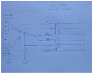
I attached a pic & cct diagram in following posts
I insulated the the phono sockets from the back panel and then routed the earths for each channel completely separately so that the only place where the earths are common between channels is in the source. I also soldered the bare 0.5mm copper wire directly onto the phono / RCA sockets for a more direct signal path.
The other factor that may explain the benefits of this mod is that the signals in the earth return legs do not now return through the aluminium back panel so avoiding potential problems with the aluminium oxide ( an insulator ) which I though may create problems with ultra fine signals of a few microvolts.
Between these two factors, of this 2nd mod, ( given the fact that the power supply is floating ) the sound, for me, was much clearer & cleaner
Many thanks to George for introducing me to this LDR concept.
I put my S&B 102mk3 back in yesterday and I know now that I can never go back to TVC's. They sound so muddled and confused when compared to these LDR's.
cheers
mike
I now feel that I have done all the mods that I can think of to my lightspeed - and I am very satisfied with the sound.
I did 2 things since I last posted.
The 1st is just a balance control instead of the trimmers. No positive impact on sound quality but more importantly no degradation - and in those circumstances - handy to have.
The 2nd mod is the earthing arrangement in the signal paths.
I attached a pic & cct diagram in following posts
I insulated the the phono sockets from the back panel and then routed the earths for each channel completely separately so that the only place where the earths are common between channels is in the source. I also soldered the bare 0.5mm copper wire directly onto the phono / RCA sockets for a more direct signal path.
The other factor that may explain the benefits of this mod is that the signals in the earth return legs do not now return through the aluminium back panel so avoiding potential problems with the aluminium oxide ( an insulator ) which I though may create problems with ultra fine signals of a few microvolts.
Between these two factors, of this 2nd mod, ( given the fact that the power supply is floating ) the sound, for me, was much clearer & cleaner
Many thanks to George for introducing me to this LDR concept.
I put my S&B 102mk3 back in yesterday and I know now that I can never go back to TVC's. They sound so muddled and confused when compared to these LDR's.
cheers
mike
Try moving chokes
Mike,
I t is most likely just in my mind, but I liked the chokes in mine connected directly to pots. This way there is a reg, CL load. Itried running one choke to each channel and also one to hot and another on ground. I could not hear any differences so used one for hot and the other for ground.
I do not completely understand your grounding, but isolating the signal from the power is one of the great things that these allow.
Bettering a S&B TVC is quite a testomonial. I have listened to a couple, but never at home where a good comparison could be made.
One thing I like about the TVC is the current ratio changes as the volume is lowered. That has to be beneficial at lower level listening.
Wonder what the reflected impdeance is as the turns ratio varies?
And another plug for Georgehifi. If you system can deal with a passive, you need to try one of the Lightspeeds. The 400.00 or so may be the best purchase you make this year.
George
Hi George,
I like your idea with the chokes and will try it. Also the ultimate filtering mod would be some small caps across the actual LED's.
The other things about the power supply that can mess things up is the resonance and RF noise, that the diode switching causes, backing up into the mains supply. A CRC filter on the input to the transformer helps with this. Also snubbers to reduce the frequency of, & damping of, this resonance.
To get best effect from this every piece of equipment plugged in needs this arrangement.
Caps have to be rated for mains voltage.
TVC comparison:
Not everyone looks for the same in hi fi sound - some prefer a less detailed smoother sound.
My idea is to carry on resolving detail as much as is possible and ultimately the details resolve into smoothness where smoothness is required.
If this is the goal then I believe this LDR volume control is the best option that I am aware of at present.
I have never heard trumpets & strings rendered so realistically not to mention cymbals. In fact the whole things just sound very honest.
cheers
mike
Mike, I echo your observations, and share your values: the more detail the better if smoothness can be had. I've increased detail in my system successfully over the years, but ultimate smoothness eluded me until I installed the Lightspeed which, for its part, handily beat my silver wire TVC (took 5 seconds' listening to conclude such). The TVC was my reference among passives, but was muddy, veiled and slightly harsh by comparison (dielectric effects of the transformer wire? the sound of switches?). As to the Lightspeed, I'd never heard a cymbal reproduced realistically before installing it.
I also separated signal and psu grounds to good effect. I also swapped out the 5V regulator for a Jung super regulator, to good effect. I then added a choke + film capacitor bypasses across the LEDs.
I also separated signal and psu grounds to good effect. I also swapped out the 5V regulator for a Jung super regulator, to good effect. I then added a choke + film capacitor bypasses across the LEDs.
")
serengetiplains said:I've increased detail in my system successfully over the years, but ultimate smoothness eluded me until I installed the Lightspeed
Tom - what source equipment are you using ?
mikelm said:My inductors are 0.05mH from parts express ( 255-200 ) so they are not dealing with low frequency noise. I am still experimenting with position.
I would suggest about 1uF directly across all 4 LEDs
cheers
mike
Sorry I'm not getting this, where's the inductor located? in the PSU for filtration purposes?
And the 1uF across the pins 1 & 2 ?
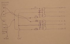
here is my circuit diagram with caps added.
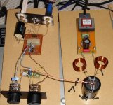
you can see where my inductors are at present my looking at the picture of my current setup ( a few posts up )
I will experiment and see it other places sound better and will post if I notice ans improvements.
George - ( Houston ) may explain more where his are located I did not quite get it either yet
mike
Attachments
- Home
- Source & Line
- Analog Line Level
- Lightspeed Attenuator a new passive preamp