You know what? I bet the 'difference' people hear, including me, is that one of the Lightspeeds has a different impedance than the other. That DOES sound different. Not always better or worse, but definitely different.
No it's not that, as the swap over is done on the fly while playing a CD and the volume level is not touched when we do this, and then plug the battery pack and it comes back up to the same level because the 5vdc reg is still in the circuit and the impedance stays the same.
(you can pull the wall wart power on the production Lightspeed Attenuator and the volume just goes down to zero and then comes back up when powered up again)
Cheers George
Banned
Joined 2002
I think i might have to buy one of these.! George shed a little price ?
Sorry one of what?
The production Lightspeed Attenuator (go to my web site and send an email to me for shipping/pricing) Optus Member Website - georgehifi
Or the Lithium battery/charger pack
(go to ebay and search "12v rechargable Lithium")
Cheers George
Hi George,
The power supply adapter shown on your site is capable of producing 12 VDC @ 300mA. I am having a FRIWO plug-in adapter (EDV1882753) that can produce 12 VDC @ 270mA. Will that be sufficient for the light speed ?
I am planning to use the TI chip set for getting the regulated supply of 5 VDC from the 12 VDC supply.
Please suggest...
Best regards,
Bins.
Hi George,
The power supply adapter shown on your site is capable of producing 12 VDC @ 300mA. I am having a FRIWO plug-in adapter (EDV1882753) that can produce 12 VDC @ 270mA. Will that be sufficient for the light speed ?
I am planning to use the TI chip set for getting the regulated supply of 5 VDC from the 12 VDC supply.
Please suggest...
Best regards,
Bins.
Yeah that's fine, if you make the Lightspeed Attenuator as per my circuit posted a few times in this topic , it only consumes the figures in post #2711
Cheers George
Is this ok to use with PGA:
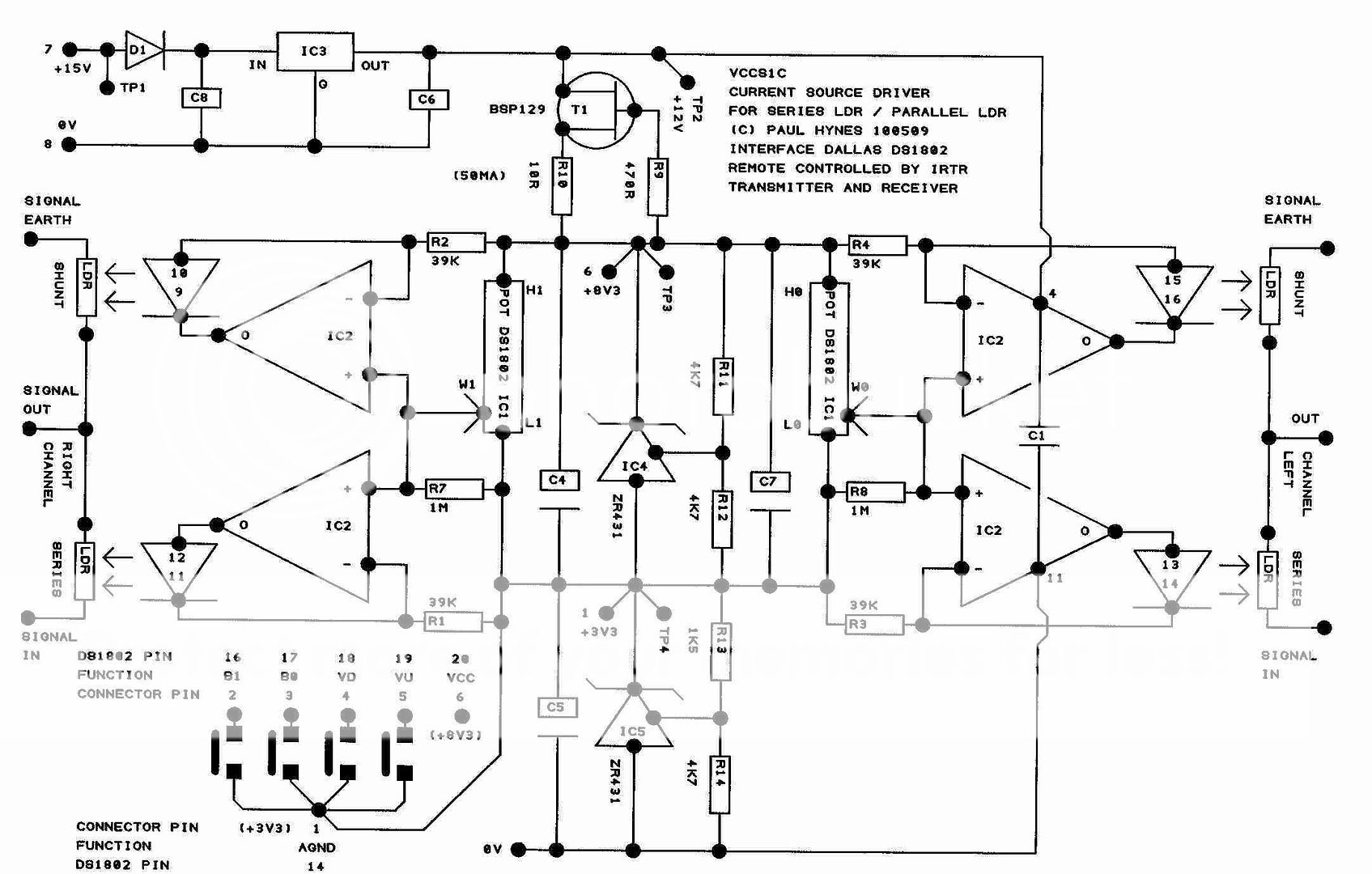
Voltage Controlled Current Source - Current Servo
According to the datasheets, Vc and Vp are the same, for R3: 125 Ohm is ok. But why does it start Photocell Resistance vs. LED Current from 0.1mA?
If not, what voltage controlled current source could I use ? Also are there ideas to digitally control this?
For this R3 would have to a variable resistor of some kind. Rheostat or trimmer or pot. I would want to drop either voltage or current but to drop both at the same time might be drastic as far as volume change. You need higher than .1mA and probably this circuit can provide that with different resistor values. You can control the LDRs with an opamp based power supply easily. This might not be the best one, but its a start and might be fun to try. Try it with LEDs first and you can SEE what is happening.
Uriah
Uriah
Web Order #:2965282
Order Date:10/26/2009
Order Status:Shipment Pending
Mouser #: 700-DS1802
Mfr. #: DS1802+
Desc.: Digital Potentiometer ICs IC POT DL AUDIO TAP W/PB
3 Pending Pending <--------------- Here....
Called to see about the "pending" status. They tell me they are back ordered until JANUARY 2010!!
Order Date:10/26/2009
Order Status:Shipment Pending
Mouser #: 700-DS1802
Mfr. #: DS1802+
Desc.: Digital Potentiometer ICs IC POT DL AUDIO TAP W/PB
3 Pending Pending <--------------- Here....
Called to see about the "pending" status. They tell me they are back ordered until JANUARY 2010!!
For this R3 would have to a variable resistor of some kind. Rheostat or trimmer or pot. I would want to drop either voltage or current but to drop both at the same time might be drastic as far as volume change. You need higher than .1mA and probably this circuit can provide that with different resistor values. You can control the LDRs with an opamp based power supply easily. This might not be the best one, but its a start and might be fun to try. Try it with LEDs first and you can SEE what is happening.
Uriah
What is the other solution (current source) that all people are asking for DS1802 to use with and what is the value of DS1802 resistance, where is the current source schematic that is used with DS1802?
Thanks
Last edited:
What is the other solution (current source) that all people are asking for DS1802 to use with and what is the value of DS1802 resistance, where is the current source schematic that is used with DS1802?
Thanks
metal
way back in a thread far far away... was this (and several more posts) by maximus.
The DS1802 is a 50K log pot with 64 steps.
For the record, I am currently trying an alternative solution using an MCP42100 (and some additional components) to simulate a log taper and will post my results here when I'm happy with the results. It's just taking a while to get consistent figures....
Mike
Mike,
I like your idea and am guessing what most of it is, but I wonder if your inconsistent figures could be improved with a stable temp in your room and a digipot with a lower ppm. So a small amount of change in temp can change the value of your digipot and the LDRs at the same time. Another problem may be that the IC you have chosen can only handle 1mA over the wiper and if you want a min of 50Ohm at any point from the LDRs you probably will have to give it around 5-20mA depending on the characteristics of that particular LDR. Of course, maybe you are not dumping the current across the wiper, you might be driving something else from that digipot to control the LDRs.
Uriah
Mike,
I like your idea and am guessing what most of it is, but I wonder if your inconsistent figures could be improved with a stable temp in your room and a digipot with a lower ppm. So a small amount of change in temp can change the value of your digipot and the LDRs at the same time. Another problem may be that the IC you have chosen can only handle 1mA over the wiper and if you want a min of 50Ohm at any point from the LDRs you probably will have to give it around 5-20mA depending on the characteristics of that particular LDR. Of course, maybe you are not dumping the current across the wiper, you might be driving something else from that digipot to control the LDRs.
Uriah
Hi udaily
i'm actually using an op-amp coupled to a small jfet (BS170) to control the current.
The circuit is quite simple and will post it sometime soon.
I'm using an arduino (but any uC will do) to contol the digital pots (255 values for series and shunt each) and, at the same time using the ADC to read a voltage to achieve the required taper.
This has several advantages:
1. taking into account the different resistances of the opto-couplers
2. allow one to vary the taper (within certain limits) to one's liking
3. MCP42100 is easily controlled using SPI so could easily be used to control as many channels as required.
The slight problem I'm having is that there's alot of permutations involved and when I go back and re-check, its not giving me quite the same results, possibly as you say due to temperature differences.
My current program now goes back and re-checks the figures.
Anyways, I will post more soon....
Mike
- Home
- Source & Line
- Analog Line Level
- Lightspeed Attenuator a new passive preamp