Wow, what a thread.
This is certainly a very long one.
Thanks to georgehifi for all his support and willingness to share this with us DIY types. Not everyone is so generous.
I have an old QED PCC (passive control centre: Alps Blue based, 6 input, tape monitoring capable) that I quite like. I have this as a "back-up to a McCormack Micro-Line Drive that can be used as a full passive line stage or an active one. Depending on the equipment that I may be listening to, I select the active or passive output (completely separate circuits). I had the opportunity to speak with Steve McCormack via telephone and was pleased to find out that both the MLD and the TDL (Total Line Drive) were designed to be used completely as passive stages with the inclusion of an active output to facilitate the use of powered sub-woofers or remote amplifiers.
A friend is looking at building one (or two) of George's Lightspeed Attenuators. My audio "partner" is building one and I will most likely tag along in the adventure. As this thread is so long, and I haven't obviously read it, can these be implemented within the existing case of an integrated amplifier (a newer T-class amp)? I understand that a power supply may need to be added (or taken from the integrated amp's existing power supply and regulated), but other than that and assuming there is appropriate space to allow the retro-fit, is there a technical reason why this would not work?
This is certainly a very long one.
Thanks to georgehifi for all his support and willingness to share this with us DIY types. Not everyone is so generous.
A friend is looking at building one (or two) of George's Lightspeed Attenuators. My audio "partner" is building one and I will most likely tag along in the adventure. As this thread is so long, and I haven't obviously read it, can these be implemented within the existing case of an integrated amplifier (a newer T-class amp)? I understand that a power supply may need to be added (or taken from the integrated amp's existing power supply and regulated), but other than that and assuming there is appropriate space to allow the retro-fit, is there a technical reason why this would not work?
Thanks for your support Nanook.
Inside a cool running Tripath (class D) amp should not be a problem, only in tube amps/preamps or warm running A/B amps there is a problem with heat fluctuations inside is can effect the LDR/LED packs to cause imbalance problems, which can undo the matching/calibration.
The other thing to watch out for is some D class amps are very low input impedance, some I've seen as low as 1k which is not a good match for the Lightspeed Attenuator circuit, you need say over 20kohm input to get the best out it in this situation with short connection to the input stage.
Cheers George
thanks George.
Great. I would actually check the input impedance with the manufacturer prior to continuing on. I suppose one could always put a 20 or 30 kΩ resistor in parallel to the input if the input impedance is too low? Or a Zobel of some sort?
Inside a cool running Tripath (class D) amp should not be a problem.
The other thing to watch out for is some D class amps are very low input impedance, some I've seen as low as 1k which is not a good match for the Lightspeed Attenuator circuit, you need say over 20kohm input to get the best out it in this situation with short connection to the input stage.
Cheers George
Great. I would actually check the input impedance with the manufacturer prior to continuing on. I suppose one could always put a 20 or 30 kΩ resistor in parallel to the input if the input impedance is too low? Or a Zobel of some sort?
Sorry to correct Nanook, if you put a 20k resistor in parallel with the input resistor that goes to ground that's already there lets say it's also 20k for simplicity, what you end up with is an input impedance of 10k, which is even worse.
Now, what you can do with amps that have fet inputs/or tube is to remove the 20kohm that's already there and replace it with 47k or even 100k.
But ask your amp manufacturer before doing this to make sure that will still behave it self. As if it is bi-polar input it could get dc offset on it's output, become unstable, or the bias could change.
Cheers George
George: please no apologies required.
I asked the question to help clarify my understanding, that's all. I asked for help and you have been gracious enough to respond. Thank you.
I will email the manufacturer to check to see what the input and load impedances are of the existing volume control. Else it will be a box similar to your production model.
Last edited:
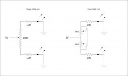
I am getting all the parts to assemble my preamp and I am having trouble sourcing the 100K dual pot.
My question is, why the dual pot? Is the reason to limit any current via the wiper? I have a hefty good quality single 100K pot. The pot is not acting as voltage divider, but as a reverse variable resistor to limit the current through the led. Am I missing something?
My question is, why the dual pot? Is the reason to limit any current via the wiper? I have a hefty good quality single 100K pot. The pot is not acting as voltage divider, but as a reverse variable resistor to limit the current through the led. Am I missing something?
Attachments
This is what you need avincenty
RV24BF-10-15R1-A100K Alpha (Taiwan) | Mouser
The reason for the 100k dual log is to share the current, and to have a nice progressive feel, slow progressive to start all the way to 2 o'clock then ramping up fast after this.
Mind you this only has this kind of progressive feel if the NSL32SR2S are a close quad matched set, if they are only pair matched it can start too quick or way too slow and have nothing/too much in either half of the rotation.
Cheers George
Thanks for the link.
Can you elaborate why a single pot doesn't accomplish the same thing? If both are linear then the resulting resistance from both sides of the wiper (or common leg on dual pot) should add to 100K. If one side has 75K, the other side will have 25K, etc... Wouldn't the matching of both sides of a single pot be closer than two opposite sides of a dual pot?
I must be missing something right in from of me.
Thanks for your assistance.
The current of two led's on the dual per track against the current of all 4 led's on a single. You must know that pots carbon or plastic don't like DC on them at the best of times, this minimizes the amount of dc.
Try it with a linear 100k dual and it will behaved very differnet, too much too fast, and you have to remember the NSL's are not linear either in their resistance and led intensity overhaul span, this has a big effect on it.
Cheers George
Try it with a linear 100k dual and it will behaved very differnet, too much too fast, and you have to remember the NSL's are not linear either in their resistance and led intensity overhaul span, this has a big effect on it.
Cheers George
Hi,
This is my very first post in this thread and I am very excited.
I've been wanting to try the Lightspeed for some time now but was put off by the process of matching the LDRs. After a hiatus of several years from DIY, I decided to take the plunge and I just put in an order for Uriah's DIY kit at Build An Amp.
I understand the circuit is a bit different from George's Lightspeed. For those who have tried both, what should I expect from this LDR premap? I am currently using a modded Cary Audio SLP-94 featuring 12au7 tubes, Shinkoh tantalum signal resistors, VTV Ultratone and Dynamicap signal caps, and a PEC carbon potentiometer. It's very musical. I do have very high expectations for the LDR preamp, however, after hearing all the positive buzz for many years. It'll probably be another ball of wax sonically, but I'm really looking forward to it.
One question I had was that I, too, am running a few variations of tripath amps. Currently I'm using a home modded amp based on the original Sonic Impact amp from several years back. My other amp in an original Charlize from diyparadise.com , and I will be finishing up a 41Hz Amp 11 at some point in the future.
I understand the LDR preamps are not a good match for these Tripath amps because of impedance incompatibilities. Because of this I am thinking of putting a version of Nelson Pass' B1 buffer directly after the LDR controller. It will be the Mesmerize, whose board can be purchased at the DIYAudio store.
Has anyone done this and would you recommend it? Are there any pitfalls to be aware of? After reading a little about the B1, I get the sense that it can run a little hot. Will this be a problem if I put both the LDR controller and the buffer in the same chassis? I understand the LDRs are affected by heat. What is your recommendation for this pairing?
As others have commented, this thread is very long. I'm in the process of working my way through it. I'm very excited about finally putting one of these preamps together.
The mesmerize boards are actually DCB1
It can get hot if you increase its PSU current. But its up to you how hot you want it. I don t even know how high the mesmerize can go in terms of hotrodding. In any case, the benefits from higher current are big, so if you want to try an ldr pot with it, I would suggest getting it as high as your chassis/heatsinks can handle and then isolate the LDRs and keep them well ventilated and isolated from the rest of the DCB1.
It can get hot if you increase its PSU current. But its up to you how hot you want it. I don t even know how high the mesmerize can go in terms of hotrodding. In any case, the benefits from higher current are big, so if you want to try an ldr pot with it, I would suggest getting it as high as your chassis/heatsinks can handle and then isolate the LDRs and keep them well ventilated and isolated from the rest of the DCB1.
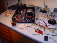
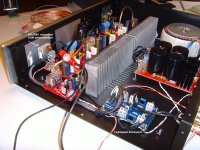
I am currently working on a remotely controlled, motorized-potentiometer version of the Lightspeed-Attenuator (see attached images).
The additional PCB contains a stepper-motor H-bridge and a PIC µProcessor to implement the RC5 - remote-control software and to
drive the stepper-motor H-bridge.
The hard- and software - design is based on an idea / project, presented by FOTIOS.
The prototype - as shown on the images - works flawlessly.
I have re-worked the layout of FOTIOS' original PCB and added a transformer for +5VDC supply and a ICSP-header
to interact with the PIC µProcessor. (This interaction is not necessarily needed!)
I want to order professionally etched PCBs soon.
If somebody of you likes this idea and wants to have as well: please send me a PM.
Best regards - Rudi_Ratlos
Attachments
Another question regarding the impedance of the Lightspeed attenuator
Hi all.
George had suggested that as long as the attenuator sees an impedance of at least 20kΩ, then the Lightspeed should not cause any problems with T-amps. So I am assuming the load that the sources see is the impedance of the 100 kΩ poteniometer used.
I have sent an email to the amplifier manufacturer and await his reply for verification regarding this question. Just trying to stay in the loop.
No the 100kohm potentiometer will not isolate the Lightspeed from seeing the input resistance of the T-amp. In Eeffect you will now be even less than the 20kokm It now becomes 16.6kohms the Lightspeed is seeing. And then the source sees this 16.6kohm with the 10kohm of the Lightspeed which becomes 6.2kohms the source sees total.
Cheers George
Cheers George
Last edited:
Guys be real real careful. Use gloves and good ventilation when handling or soldering LDRs.
http://ntp.niehs.nih.gov/ntp/roc/twelfth/profiles/Cadmium.pdf
The cadmium in/on them can cause Leukemia/other cancers.
Also see the bottom of the silonex.com page.
http://ntp.niehs.nih.gov/ntp/roc/twelfth/profiles/Cadmium.pdf
The cadmium in/on them can cause Leukemia/other cancers.
Also see the bottom of the silonex.com page.
- Home
- Source & Line
- Analog Line Level
- Lightspeed Attenuator a new passive preamp