I need some help please
I bought Uriah's Lightspeed kit, I received the kit with two 100R resistors and a single pot, not a dual.
I have read everything I can and can not figure out how to wire it together.
Can someone please draw a diagram to show how the psu, pot and LDR board is wired.
Thank you
I bought Uriah's Lightspeed kit, I received the kit with two 100R resistors and a single pot, not a dual.
I have read everything I can and can not figure out how to wire it together.
Can someone please draw a diagram to show how the psu, pot and LDR board is wired.
Thank you
Attachments
I think the single pot you have identified is the 1k multi turn used for balancing the channels at the most used part of the volume control range.
Go read the manual.
BTW,
George makes and sells the "Lightspeed".
We should not refer to anyone elses copy/clone/ripoff as a lightspeed.
LED or LDR or optical or some other name you see most used is now demanded by the Forum.
Go read the manual.
BTW,
George makes and sells the "Lightspeed".
We should not refer to anyone elses copy/clone/ripoff as a lightspeed.
LED or LDR or optical or some other name you see most used is now demanded by the Forum.
Last edited:
Hmmmm
I did find a dual pot, I must have goofed, I also found a single pot.
I am trying to build Uriah's MyRefC, a Pass DIY B1 Preamp for another chip amp, and this LDR project, I have the PSU built and can not figure out how to wire it to the LDR board and dual volume pot.
That blue pot on the board has an adjustment for something and I don't know where to find the answer.
The Manual? Where is the manual to uriah's ldr project?
I have printed and read everything I can find, I come here as a last resort.
Everything I read about looks like the attached picture. I can't find a BOM,
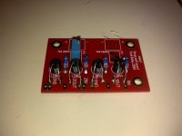
When the board and parts arrived I received what you see in the picture in the previous post, One adj 200 ohm 1004 CC, 4 LDR's, 2 100R resistors and a board.
I bought 4 100R and put then in the board
What I would like is a picture of a completed Uriah LDR to see where the wires go and to see if parts were missing from my kit.
and I won't use that word again, I will use LRD. Thank you for the advice.
Can you please help?
I did find a dual pot, I must have goofed, I also found a single pot.
I am trying to build Uriah's MyRefC, a Pass DIY B1 Preamp for another chip amp, and this LDR project, I have the PSU built and can not figure out how to wire it to the LDR board and dual volume pot.
That blue pot on the board has an adjustment for something and I don't know where to find the answer.
The Manual? Where is the manual to uriah's ldr project?
I have printed and read everything I can find, I come here as a last resort.
Everything I read about looks like the attached picture. I can't find a BOM,
When the board and parts arrived I received what you see in the picture in the previous post, One adj 200 ohm 1004 CC, 4 LDR's, 2 100R resistors and a board.
I bought 4 100R and put then in the board
What I would like is a picture of a completed Uriah LDR to see where the wires go and to see if parts were missing from my kit.
and I won't use that word again, I will use LRD. Thank you for the advice.
Can you please help?
Attachments
Your BOM is:
One dual pot.
One trimmer (don't install yet) to balance channels.
4 Resistors
4 LDRs
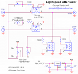
If you look at the schematic you linked, you will see that 5V feed goes to Pin 1 on one channel (A) and then is joined to pin 3 on the other channel (B). Join pins 2A and 3A together and you have a variable 5V supply on the end of that wire. Join pins 1B and 2B together and you have a second 5V supply. As you move the pot, one supply increases, while the other decreases. What we are doing with this circuit is lighting up the LDRs, but one set (A) is attenuating the signal, and the other set (B) is shunting to GROUND.
Once you have built the circuit, then measure the channels (or set them up with a scope like I did) and install the trimmer on the louder channel and tweak it down the both channels are perfectly balanced at your preferred listening volume.
I haven't seen Uriah's board, so can't be more specific, but hopefully this explanation wil make things a little clearer.
Cheers
Jon
One dual pot.
One trimmer (don't install yet) to balance channels.
4 Resistors
4 LDRs
If you look at the schematic you linked, you will see that 5V feed goes to Pin 1 on one channel (A) and then is joined to pin 3 on the other channel (B). Join pins 2A and 3A together and you have a variable 5V supply on the end of that wire. Join pins 1B and 2B together and you have a second 5V supply. As you move the pot, one supply increases, while the other decreases. What we are doing with this circuit is lighting up the LDRs, but one set (A) is attenuating the signal, and the other set (B) is shunting to GROUND.
Once you have built the circuit, then measure the channels (or set them up with a scope like I did) and install the trimmer on the louder channel and tweak it down the both channels are perfectly balanced at your preferred listening volume.
I haven't seen Uriah's board, so can't be more specific, but hopefully this explanation wil make things a little clearer.
Cheers
Jon
Last edited:
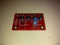
Here is a picture of Uriah's LDR Board.
Does running 5volts through the pot affect it's life?
I will try to figure out the wiring, but a diagram sure would help.
I am still not sure what to do.
Why am I not to istall the trimmer? Where is a manual?
Does running 5volts through the pot affect it's life?
I will try to figure out the wiring, but a diagram sure would help.
I am still not sure what to do.
Why am I not to istall the trimmer? Where is a manual?
Attachments
install the trimmer on the louder channel and tweak it down the both channels are perfectly balanced at your preferred listening volume.
Starter for 10...
Nope, 5V will not kill your pot. At the milliamps this circuit requires, it's no problem.
You posted the wiring diagram, Gary. It's the same old thing - maybe a different layout, but the circuit is still the same. Power to the LDRs, signal in, signal out etc. I've had a quick look at your images, but it's late here - I'll have another go tomorrow. It should be a case of plumbing in the power, signal in and out and away you go... PS Please can you show the bottom of the board?
The trimmer is only used at the end of the process. Once you have your LDR attenuator working, one channel will be (perhaps only marginally) louder than the other at your favoured listening position due to the fact that the LDRs are never PERFECTLY matched (impossible).
So, install the trimmer on the louder channel and tweak down to get a perfectly balanced sound.
HTH
Jon
Last edited:
BUILD MANUAL FOR LIGHTER NOTE PLEASE PASTE THESE LINKS TO YOUR BROWSER
Picasa Web Albums - Uriah - Lighter Note ...#
Google Docs
Google Docs
Here is all you need to know.,
I couldnt find the 2nd and 3rd ones here and took the very long route of following the pictorial
Picasa Web Albums - Uriah - Lighter Note ...#
Google Docs
Google Docs
Here is all you need to know.,
I couldnt find the 2nd and 3rd ones here and took the very long route of following the pictorial
the matched pairs get shared between the Left & Right channels.
One pair do L series and R series.
The second pair do L shunt and R shunt.
The pairs might have been marked for a preference to shunt or to series.
Clip on an aluminium heatsink between the device and the PCB, before you start trying to de-solder the LEDs & LDRs.
One pair do L series and R series.
The second pair do L shunt and R shunt.
The pairs might have been marked for a preference to shunt or to series.
Clip on an aluminium heatsink between the device and the PCB, before you start trying to de-solder the LEDs & LDRs.
How are the matched set (2) LDR's installed?
Gary, I think you have installed them correctly - or not depending on that pic I reference below.
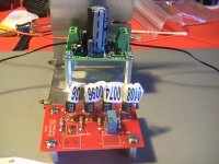
Looking at your earlier board picture, post 3266, LDRs 1 and 2 are the Left/Right Series devices. LDRs 3 and 4 are the Shunt devices.
Is the pic in post 3262 of your LDR vol control? If so, then the LDRs tagged 0036 and 0074 are indeed Left and Right Series, and the LDRs tagged 0096 and 0108 are your Shunt LDRs. These are near enough values, and will just require a bit of trimming when you get up and running. You don't need the trimmer fitted yet. In fact, on closer inspection, I see Uriah has provided a facility to trim both the series and shunt LDRs for balance, but that isn't important right now.
However, if the pic in post 3262 is not of your rig, and having had another look at your note in post 3270, I think I'm with you now! You need to install one matched pair in LDR1 and LDR2 (series) and then the other matched pair in LDR3 and LDR4 (shunt). Your bracketing in your diagram looks the same to me, but to underline: you need one matched pair as the series LDRs and the other matched pair as the shunt LDRs.
Are not the +- boxes behind the trimmers for connecting your two 5V feeds from your dual log pot?
HTH
Jon
Yes, post 3262 is my picture.
Where do the wires go? I am totally confused about how the dual pot is wired to the board, the manual confuses me.
Are the 4 resistors all 100R? two were missing and one schematic shows all 4 being 100R but the manual stated that two are some other value.
Where do the wires go? I am totally confused about how the dual pot is wired to the board, the manual confuses me.
Are the 4 resistors all 100R? two were missing and one schematic shows all 4 being 100R but the manual stated that two are some other value.
OK, in which case, I think your LDRs are installed correctly.
Pot wiring I explained here:
http://www.diyaudio.com/forums/anal...nuator-new-passive-preamp-66.html#post2201140
The two 5V feeds are connected on the board as the + points. The schematic will tell you which of the two goes where - i.e Pot channel A goes to the + on the box behind the "series bal" trimmer. Pot channel B goes to the + on the box behind the "shunt bal" trimmer.
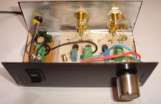
Connect your RCA IN hot lines to 1IN and 2IN, and connect your RCA OUT hot lines to 1OUT and 2OUT. Connect all ground/cold leads together at the same point (i.e. a star ground).
If you do all of this, your LDR vol control should work. Then we'll go through the channel balancing. I don't know what circuit Uriah used, but it might be that if you desolder the trimmer for now, you will need to solder in a jumper to keep continuity.
WRT the resistors, I use George's original schematic, and all 4 are 100R. I recall some conversation about using different values to tune the output impedence of the device (or something), but I'm afraid I can't shed any light on this particular subject. Until Uriah can give you more specific guidance, I'd just stick with the 4 x 100R resistors.
Jon
Pot wiring I explained here:
http://www.diyaudio.com/forums/anal...nuator-new-passive-preamp-66.html#post2201140
The two 5V feeds are connected on the board as the + points. The schematic will tell you which of the two goes where - i.e Pot channel A goes to the + on the box behind the "series bal" trimmer. Pot channel B goes to the + on the box behind the "shunt bal" trimmer.
Connect your RCA IN hot lines to 1IN and 2IN, and connect your RCA OUT hot lines to 1OUT and 2OUT. Connect all ground/cold leads together at the same point (i.e. a star ground).
If you do all of this, your LDR vol control should work. Then we'll go through the channel balancing. I don't know what circuit Uriah used, but it might be that if you desolder the trimmer for now, you will need to solder in a jumper to keep continuity.
WRT the resistors, I use George's original schematic, and all 4 are 100R. I recall some conversation about using different values to tune the output impedence of the device (or something), but I'm afraid I can't shed any light on this particular subject. Until Uriah can give you more specific guidance, I'd just stick with the 4 x 100R resistors.
Jon
Last edited:
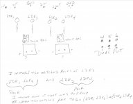
referring to post3270.
LDR1 & 2 are the series. These are one matched pair.
LDR3 & 4 are the shunt. These are the other matched pair.
1IN & 1OUT are one channel
2IN & 2OUT are channel 2.
If you have fitted a matched pair to positions 1 & 3 then you have a pair in channel 1 and the other pair in channel 2.
Don't overheat them during de-soldering.
Update on remote control
Folks,
Back in post 3091 I mentioned the possibility of using the referenced IR remote control "kit' available on Ebay to possibly remotely operate the LDR's in the Lightspeed "kit". Well I ordered and got the Remote Control and just spent a few hours figuring it out.
Turns out that it uses a 6 gang, logarithmic 100K (each gang), motorized volume control (pot), along with 5 channels of input switching (via relays). I figured out the wiring to the pot and was able to separate-and-wire-out two sections of it to give me effectively one section that increases resistance for CW travel of the pot (to turn off the shunt LDRs) while the other simultaneously decreases resistance (to turn on the series LDRs)
I'm now awaiting delivery of Uriah's matched LDR's and PC board to mount, wire and try out the whole package to see if it will work - how it "sounds", and if it's stable over time.
Will let you know.
Charles
Have been busy with new baby in the house and have not even checked emails yet. If anyone tried to contact me that way please accept my apology.
ppcblaster you have my phone number so feel free to use it and we can discuss your questions.
Andrew this circuit is far from any copy/clone/ripoff of George circuit and anyone who sees it knows that. Using LDRs to attenuate volume does not constitute a ripoff.
As far as my Lighter Note is concerned I will not discuss it in George's thread and hope that the rest of you will see fit to either start a new thread or simply contact me.
Uriah
No such thing as zero with the LDRs. They go down to around 40R safely and some, as they are all unique, will go lower safely. One of my builds went to 26R but I have had others fizzle at 26R. Lower gain amps or lower efficiency speakers help a lot in this case. Right now my MyREFC and 96db speakers are a mean combination with a Lightspeed. To loud. Same speakers and same Lightspeed with lower gain tube amp is no problem.
Sooooo. should I take this to mean that you have speakers?!?!
Thanks for the congrats") she's a beauty. I am sure you have seen the pictures on Picasa.
she's a beauty. I am sure you have seen the pictures on Picasa.
And thanks Woodturner for the congrats as well. If anyone is wondering my wife just had a baby 12 days ago. 6lbs little girl. Her name is Norah.
Sooooo. should I take this to mean that you have speakers?!?!
Thanks for the congrats
she's a beauty. I am sure you have seen the pictures on Picasa.And thanks Woodturner for the congrats as well. If anyone is wondering my wife just had a baby 12 days ago. 6lbs little girl. Her name is Norah.
- Home
- Source & Line
- Analog Line Level
- Lightspeed Attenuator a new passive preamp