Comparing acuracy of RIAA^-1
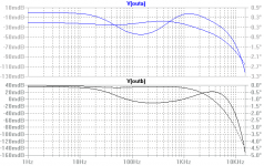
I've put these into the widgidizer -- the transfer function has the exact RIAA time constants -- thought folks would like to see how the inverse RIAA designs stack up. The gain block is to normalize results -- compare the variability of the bode plots:
First Williamson:
then Lipshitz-Jung:
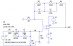
then two suggested (one a few minutes ago by Nuvistor):
I am sure there are more and I will post them as I see them.
I've put these into the widgidizer -- the transfer function has the exact RIAA time constants -- thought folks would like to see how the inverse RIAA designs stack up. The gain block is to normalize results -- compare the variability of the bode plots:
First Williamson:
An externally hosted image should be here but it was not working when we last tested it.
then Lipshitz-Jung:
An externally hosted image should be here but it was not working when we last tested it.
then two suggested (one a few minutes ago by Nuvistor):
An externally hosted image should be here but it was not working when we last tested it.
An externally hosted image should be here but it was not working when we last tested it.
I am sure there are more and I will post them as I see them.
Hi jackinnj -
I guess the "2nd DIYAUDIO suggested" is attributed to me. This appears to be the preamp equalization network for "El Cheapo" and is not my inverse RIAA RC network.
My inverse RIAA network values were chosen for the polystyrene and silver-mica capacitors I had, and is meant to drive a 47k load. The 1050 ohm resistor is the sum of 1k and 50 ohm generator source resistance.
I see that my description of the inverse RIAA was not correct, that description is correct for preamp equalization. I should have said: This inverse RIAA includes the "Neumann" 3.18us or 50kHz lag in addition to the usual 50/2122Hz leads and 500Hz lag. The LTSpice files are as I intended.
Your transfer function clearly uses the standard constants only, the output of a standard preamp will fall off by 0.5dB from 1kHz to 20kHz when driven by inverse networks with the added 50kHz constant, this is consistent with your result.
A spreadsheet that is designed for active RIAA feedback networks but can be adapted for inverse RIAA networks can be found here.
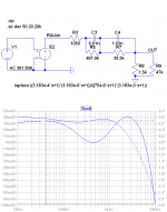
Below is my inverse RIAA network driven as in your examples with the 50kHz constant added and with a 47k load. Output is within 0.07dB from 20Hz to 15kHz, 0.13dB to 20kHz. Removing the 47k adds 0.02dB, adding 220pF load adds 0.07dB, practically the same
I guess the "2nd DIYAUDIO suggested" is attributed to me. This appears to be the preamp equalization network for "El Cheapo" and is not my inverse RIAA RC network.
My inverse RIAA network values were chosen for the polystyrene and silver-mica capacitors I had, and is meant to drive a 47k load. The 1050 ohm resistor is the sum of 1k and 50 ohm generator source resistance.
I see that my description of the inverse RIAA was not correct, that description is correct for preamp equalization. I should have said: This inverse RIAA includes the "Neumann" 3.18us or 50kHz lag in addition to the usual 50/2122Hz leads and 500Hz lag. The LTSpice files are as I intended.
Your transfer function clearly uses the standard constants only, the output of a standard preamp will fall off by 0.5dB from 1kHz to 20kHz when driven by inverse networks with the added 50kHz constant, this is consistent with your result.
A spreadsheet that is designed for active RIAA feedback networks but can be adapted for inverse RIAA networks can be found here.
Below is my inverse RIAA network driven as in your examples with the 50kHz constant added and with a 47k load. Output is within 0.07dB from 20Hz to 15kHz, 0.13dB to 20kHz. Removing the 47k adds 0.02dB, adding 220pF load adds 0.07dB, practically the same
Attachments
")
Onvinyl said:One final question: how do you get the clean *.png files out of ltspice?
Rüdiger
From LTSpice: Select the display frame you want to capture, then choose Tools > Copy bitmap to Clipboard. Note that this only captures the active display frame.
Then paste the bitmap to a graphics program, I used Microsoft Photo Editor, part of the Microsoft Office suite, but any graphics editor that can output .png should work.
The only problem I had with this was controlling the bitmap resolution, a full size display frame was too large for the diyaudio upload, I ended up opening multiple frames and tiled them before selection.
.png gives the smallest file sizes, followed closely by .gif, either one is fine for line drawings. .jpg is not a good choice for line drawings.
- Status
- This old topic is closed. If you want to reopen this topic, contact a moderator using the "Report Post" button.
- Home
- Source & Line
- Analog Line Level
- SPICE transfer function for RIAA testing