Over what frequency range? Most analog delays are only good over a certain frequency range
IE: If we had a circuit with an analog delay of 1usec over 20Hz - 20kHz, and we used it outside of that range (let's say 30kHz), the delay would not be 1usec anymore (could be more or less).
Another issue is that analog delays usually have amplitude gain nonlinearity over frequency (in our previous example, the voltage gain at 20Hz is probably not the same as the voltage gain at 20kHz).
==> Are you sure you can't digitize your source and use a digital delay? I would think that a digital delay would probably be MUCH more accurate and precise.
i didn`t know that.
i want to use it to the output of a crossover.
the frequency ranges are 300-5000 for the mid and 5000 -20000 for the tweeter.
i don`t want to digitize it again.
i was looking for a way to improve quality easily.
if it can`t be done i will wait to get a digital xover.
i want to use it to the output of a crossover.
the frequency ranges are 300-5000 for the mid and 5000 -20000 for the tweeter.
i don`t want to digitize it again.
i was looking for a way to improve quality easily.
if it can`t be done i will wait to get a digital xover.
dnsey said:Why not just align the drivers? At most, you need 20cm difference.
Because it only makes the on-axis response correct. The only correct solution is electronic delay.
It is possible to achieve analogue delay of up to about 1ms. I used to use LC analogue delays that could do this. They were very large, hand made, and consisted of about one hundred inductors (all carefully adjusted to precise values) and a similar number of polystyrene capacitors (also adjusted). These delays were used in conjunction with phase equalisers to correct delays from routing stereo signals via wildly different paths from an outside broadcast to London Broadcasting House.
Delay is best done digitally - it's the main argument for using a digital crossover.
my drivers are placed on a baffle but their acoustical centers
are about 2cm for woofer-mid and about 1cm for mid-tweeter.
there is only one way to solve this problem.
electronic delay.
aligning the drivers would cause more problems than it solves.
sloping the baffle would cause listiening the drivers of axis.
my crossover is 4th order linkwitz riley.
phase invert is not the same with delaying the signal.
it improves frequency responce but impulse responce
and stero image have problems.
mazurek mid - tweeter alignment is more critical than woofer-mid
i checked out the linkwitz link but still didn`t solve my problem.
i don`t know how to make an adjustable circuit.
In this post I attached a spreadsheet that includes calculations for an all pass delay. pick a standard cap value, and adjust the resistor to get the offset you want. You may need to add two stages, although 10mm ought to be achievable with just one.
Simply correcting for the difference in acoustic centers will get you close, you can get it better by tweaking slightly to minimize the phase shift between drivers at the XO point. Smoothly changing seems to be more important than an exact match.
Simply correcting for the difference in acoustic centers will get you close, you can get it better by tweaking slightly to minimize the phase shift between drivers at the XO point. Smoothly changing seems to be more important than an exact match.
Use Linkwitz's #4 - Delay correction.
Starting values depend on your crossover frequency of interest. With the values shown in Linkwitz's example, you are about right if your XO is at 2500 Hz. I'd start there with a 5 K pot. If you cannot get enough delay, swap the position of C and R or reverese teh connections to the tweeter. (There is nothing magic about the polarity, what matters is getting the diaphragm moving the right direction at the right time. You can invert the signal electrically or electronically. Once you find the right resistor value, replace the pot with the equivalent resistor. The other resistors in the circuit ought to be the same as R for minimum DC offset.
How did you measure the acoustic centers? the centers of the voice coil gaps are an approximation.
Please be aware that allpass filters do not actually delay the input signal but they shift the phase. With clever choice of dimensioning an allpass can be made to behave like a delay up to a certain frequency. The higher this frequency - for a given delay value - the longer the allpass filter.
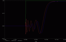
Enclosed you can see the step response of a 10th order allpass with a delay of 100us approx. The allpass is consisting of five equal 2nd order inverting allpass sections witha a Q of 0.5 (therefore the output signal is inverted).
The same delay can be achieved with 10 first-order allpass sections like the ones shown on SL's homepage.
2nd order sections have the advantage that Q-values can be chosen at will and they should have a slight THD+N advantage -but first order sections are less demanding regarding loop gain of the op-amps.
One can clearly see that the circuit doesn't give a perfect delay and that higher frequencies are delayed less than the lower ones.
I used a 40 kHz lowpass after the filter in order to emulate the upper cutoff of a tweeter. This signal is shown as well and it looks a little better then the one coing from the allpass directly.
Green: Input step
Red: Allpass output
Blue: lowpass- filtered allpass output
Regards
Charles
Attachments
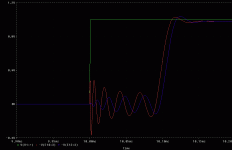
Here you can see the result for a 10th order Bessel allpass of the same delay approx. The result is definitely better due to less group-delay distortion. But this comes at a price: Only 2nd order sections can be used and tighter parts tolerances are asked for.
Trace colours same as before.
Regards
Charles
Trace colours same as before.
Regards
Charles
Attachments
- Status
- This old topic is closed. If you want to reopen this topic, contact a moderator using the "Report Post" button.
- Home
- Source & Line
- Analog Line Level
- adjustable time delay

