Hi to everyone!
I got a question concerning an analog switch with a 4053.
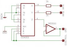
I built up the switch like you can see in the attachment.
The sense of building up the switch like that is, that the unused
input is connected to GND to avoid crosstalk.
The switch works pretty fine, but sometimes i get noise (oscillation?!?, perhaps capacitive coupling?) at the output. Touching the connection between the 4053 and the OP stops the noise. First the signal is similar to half-triangle, and sometimes the stage latches at Vneg.
I guess that the connection between the 4053 and the OP is too high Z and there is capacitive coupling or oscillation?!?
I'm not very experienced in analog circuit design, so perhaps
some of the cracks in here could give me a hint how to avoid
these problems?
Greetz and thanx in advance!
kmt
I got a question concerning an analog switch with a 4053.
I built up the switch like you can see in the attachment.
The sense of building up the switch like that is, that the unused
input is connected to GND to avoid crosstalk.
The switch works pretty fine, but sometimes i get noise (oscillation?!?, perhaps capacitive coupling?) at the output. Touching the connection between the 4053 and the OP stops the noise. First the signal is similar to half-triangle, and sometimes the stage latches at Vneg.
I guess that the connection between the 4053 and the OP is too high Z and there is capacitive coupling or oscillation?!?
I'm not very experienced in analog circuit design, so perhaps
some of the cracks in here could give me a hint how to avoid
these problems?
Greetz and thanx in advance!
kmt
Attachments
Your circuit is basically OK.
Exactly which version of the 4053 are you using?
What are your supply rails?
What are the control signal "0"s and "1"s?
I would reduce the 2K resistors
The NE5532 common mode range is much lower than its supplies, not a good choice. If it is running off higher supplies than the 4053 there may be some power supply sequencing problems.
Hi!
I don't have the circuit in front of me, so I can't tell you the
exact version of the 5532 yet, but I'll have a look when I return
home today.
My supply rails are +/- 5V, the digital Part is controlled
with 0V / 5V.
I didn't take a lower value for the resistors, because
I was afraid of the non-linearity of the conductance of the 4053.
Am I right, or is that fact neglectible?
Greetz from Hamburg to Kuala Lumpur
kmt
The current flowing through the 2ks will be negligible because the load is just capacitance. They do make the circuit more likely to pick up signal so bypass them.
The CD4053 and the 74HC4053 should both work in this circuit, newer types like the 74LV4053 don't work with negative Vee any more.
If you are stuck with +/- 5 on the opamp you really need a type that works with inputs near +ve supply
The CD4053 and the 74HC4053 should both work in this circuit, newer types like the 74LV4053 don't work with negative Vee any more.
If you are stuck with +/- 5 on the opamp you really need a type that works with inputs near +ve supply
not sure i'm understanding exactly what your symptoms are, but i'm thinking a couple of things to throw out, for what it's worth:
1. maybe you need a resistor from the opamp non-inverting input to ground (non-inverting input needs a dc path to ground at all times). a high value resistor to minimize loading on the switch helps keep the distortion down. this leads into the second thought ...
2. maybe a different op amp would be better in this position. i don't know the rest of your system needs/requirements, but maybe a nice jfet input part might be good. as someone indirectly already pointed out, make sure the opamp has the specs you need at the rail voltage you use. the performance of many opamps drops off a cliff when the rails go down to +/-5v.
3. ok, ok. i really had 3 thoughts instead of a couple")
any thoughts about using a nicer analog switch than those old ones? AD, Maxim and Siliconix/Vishay have some nice ones that can run at +/-15v rails, if you can do it.
good luck,
mlloyd1
1. maybe you need a resistor from the opamp non-inverting input to ground (non-inverting input needs a dc path to ground at all times). a high value resistor to minimize loading on the switch helps keep the distortion down. this leads into the second thought ...
2. maybe a different op amp would be better in this position. i don't know the rest of your system needs/requirements, but maybe a nice jfet input part might be good. as someone indirectly already pointed out, make sure the opamp has the specs you need at the rail voltage you use. the performance of many opamps drops off a cliff when the rails go down to +/-5v.
3. ok, ok. i really had 3 thoughts instead of a couple
any thoughts about using a nicer analog switch than those old ones? AD, Maxim and Siliconix/Vishay have some nice ones that can run at +/-15v rails, if you can do it.
good luck,
mlloyd1
What is the supply of the 4053? You should feed +5V to Vdd, 0V to Vss and -5V to Vee in the config you use.
The resistor to gnd at the non-inverting input is a good idea.
Normaly if you use those switches, you use an inverting opamp and put them at the inverting input of the opamp. Less voltage over the swich that way.
A 5532 works fine down to +/-3V so that should be ok.
The resistor to gnd at the non-inverting input is a good idea.
Normaly if you use those switches, you use an inverting opamp and put them at the inverting input of the opamp. Less voltage over the swich that way.
A 5532 works fine down to +/-3V so that should be ok.
Hi!
Many thanks to everyone for these helpful thoughts!
The power supply for the 4053 is correct: +5V / 0V / -5V,
and (normally) the switch works fine. Using another chip
is unfortunately not possible, because I'm troubleshooting
an existing PCB, and a replacing ic would have to use the
same pin assignment as the 4053. But the resistor
between Op-Amp input and GND could be a possible solution.
I'm quite shure there's a high Z connection between 4053 and
Op-Amp which picks up noise or oscillates because of capacitive
coupling to somewhat....
I'll have to check, but it could be possible that the OP's
power supply rails are +/-15V. The Power supply of the
4053 is surely 5V, 0V, -5V.
Perhaps I should try to describe the fault some more:
normally, the switch works fine, no crosstalk, no (audible)
distortion. But after a short time of operation, there is
loud noise at the output. Sounds similar like a bad power
amplifier with someone switching the lights in the room on/off/on/off and so on. When I look at the output, I can see
first a sawtooth waveform at negative level, later the
signal latches at -5V. Perhaps I can post a picture of the
signal on wednesday. The signal form changes when I come
with my finger near to the 4053, NOT touching it.
When I touch the non-inverting input (connected to the
output of 4053), the error stops immediately, and the
device returns to normal operation. After some
minutes, the game starts again. Could be that
I decharged the OPamps input with my finger?
Trying to learn some more: mlloyd, why do You think a
JFET OP could be better? Less input current?
and second: why is it important to have a DC signal path
to ground from non-inverting inputs of OPs?
Greetz and thanx
kmt
Is this when there is nothing connected to the selected input? If so, then it is the 5532 trying to pull his input bias current and having nothing to take it from. So it will drift to -5V, where the inputprotection of the 4053 starts conducting enough to allow the 5532 to pull this.
If that is the case, then a 100k resistor from the non-inverting input to analog gnd will likely solve it.
To answer your last questions:
1) yes, that is what mlloyd is thinking about. Jfets draw less current on their input pins, so it could solve it, or it could just make the time before it happens longer.
2) all opamps draw current into the input pins. This you can find in the specs as "input bias current". It is highest for bipolar opamps (like the 5532) and lower for the (j)fet opamps. Normally this is nothing to worry about unless you are working with very high impedance sources/circuits and/or need to have a very low offset. So you have to give the opamp a chance to draw this current. Otherwise, this current is going to drain the parasitic cap at the input in and you will see the output drift towards a supply rail and get stuck there. (very much like what you see...) A resistor to gnd, or a feedback resistor to the output can both play that role. This is so for both inputs!
@Havoc:
A huge thanks for the explanation! Makes some things much
clearer now.
@davidsrsb:
sorry, I haven't been able yet to look at the circuit (I work
for a german broadcast station and had a lot unexpected work this week), but I can assure You that I didn't use
a 74..4053. Either HEF4053 or CD4053 or HCF4053. As I remember, I downloaded the datasheet from the manufacturer and everything seemed to be ok. I'll take my multimeter and have a look at the on resistance. I hope I'll manage that on wednesday
evening (if the NDR doesn't give me overtime
Greetz
kmt
Something else to think about. The 4000 series analog switches have very poor off isolation - only about 50dB. This is improved if the load resistors are very low but then the distortion rises rapidly as the load falls.
If you have the opportunity to redesign the circuit (not always possible) and you want solid state switches then have a look at the Analog Devices SSM2402 and SSM2404. These have much greater off isolation (due to a series-shunt-series switch configuration) and much lower charge injection (you will likely notice an audible click each time the 4053 switch changes state)
Definitely install a resistor on the opamp input ( >10k to minimise loading/distortion). If you want to increase this resistor further then choose a pin-for-pin compatible opamp with much lower bias current. The NE5534 is still useful but its Ib specifcation is in the dark ages - which is when it was born!
These switches are also very susceptible to failure from voltage spikes on the power supply. And therefore, likely to exhibit strange behavious if 'merely' damaged by these spikes rather than actually destroyed.
I have spent just a little time removing all the 4000 series multiplexers from a large tester to imrpove performance and relaibility. I would NOT recommend thing for anythign but the most cost sensitive project.
Hi!
Perhaps I should really change the 4053. The problem
is, that I would have to change these in an existing circuit,
so I would have to search an ic with exactly the same pin assignment and voltage range. Does someone know
such an ic?
The off isolation isn't a problem in my circuit because
of the circuit design itself. Connecting the switches in
the way I did improves the off isolation for the "not used" input
dramatically.
The voltage spike problem could be an issue. I'll have to check
in my free time.
@VivaVee: do you mean a resistor in the signal path from
the switch to the OP, or a resistor from the OPs input to GND?
Greetz from Hamburg
kmt
@VivaVee: do you mean a resistor in the signal path from
the switch to the OP, or a resistor from the OPs input to GND?
I mean from the OP input to ground. As suggested above, check out Maxim. They have improved versions of the 4051/2/3 that are plug-in replacements. They actually specify the charge injection which suggests that that characteristic is actually an improvement over the standard devices. The on-resistance is certainly much lower and better matched between channels.
Re: Maxim switches - You may be able to get samples from the Maxim website.
MC14053 are ok at +/-5V. These are very old devices with limited ESD protection and some tendancy to latch up if the inputs are driven beyond the supply rails - I would have a good look at the two inputs.
Another thing to check is that the control input is <0.5 V low and >4.5V high, TTL levels are not enough for this device.
I consider your circuit to be properly designed to work even with the limited OFF isolation of a 4053 switch because of the series/shunt arrangement. The NE5532 should be OK in this appication, it's nothing special but good enough.
- Status
- This old topic is closed. If you want to reopen this topic, contact a moderator using the "Report Post" button.
- Home
- Source & Line
- Analog Line Level
- Analog Audio switch with 4053