High school electronics was long ago, so bear with me.
I'd like to build a summing box that accepts the outputs from a PC soundcard and mixes them down into a single mono signal that I can feed to an amp which drives an array of tactile transducers. The application here is a racing simulator cockpit.
Aside from driving the tactile transducers, I am splitting the analog signals from the soundcard with Y cables and thus also feeding a Klipsch 4.1 ProMedia speaker system.
Right now I am combining everything for my transducers using a Behringer analog mixer. It's big and in the way and channels are starting to fail. So I want to replace it with something more compact that I can hide away. I don't need the faders or other features of the mixer. I just need a way to combine the 4.1 audio into one mono signal. Preferably something small I can tuck out of the way.
My thought was to build a simple passive summing circuit using resistors but I am calculating that I will lose maybe 15dB or more of the signal and I'd need some kind of preamp to bring it back up closer to line-level for it to be useful.
My next thought is to include an inverting op-amp to bring the gain back up, and maybe include a capacitor in parallel with the feedback resistor to serve as another bit of low-pass filtering.
The transducer array is 4ohms and can handle 80W rms. Right now I'm driving them with one of the little crappy amps that came with the transducers as part of the Aura Interactor toy back in the 90s. It's probably not putting out much more than 10W without starting to break up in an unacceptable way. So the other thing I'd like to do is replace that toy amp with something that has a bit more clean power.
The amps I have been considering are ~ $15 USD and based on the TPA 3116 chip. Anecdotally, these can make ~ 50W rms into 4ohms with < 1% thd from a 24V 4A wall-wart.
My next thought after that was why not put the summing amp and power amp in the same box and power everything off the same power supply?
What I am hoping for from you folks is some guidance about
Thanks for reading and any guidance you can provide.
I'd like to build a summing box that accepts the outputs from a PC soundcard and mixes them down into a single mono signal that I can feed to an amp which drives an array of tactile transducers. The application here is a racing simulator cockpit.
Aside from driving the tactile transducers, I am splitting the analog signals from the soundcard with Y cables and thus also feeding a Klipsch 4.1 ProMedia speaker system.
Right now I am combining everything for my transducers using a Behringer analog mixer. It's big and in the way and channels are starting to fail. So I want to replace it with something more compact that I can hide away. I don't need the faders or other features of the mixer. I just need a way to combine the 4.1 audio into one mono signal. Preferably something small I can tuck out of the way.
My thought was to build a simple passive summing circuit using resistors but I am calculating that I will lose maybe 15dB or more of the signal and I'd need some kind of preamp to bring it back up closer to line-level for it to be useful.
My next thought is to include an inverting op-amp to bring the gain back up, and maybe include a capacitor in parallel with the feedback resistor to serve as another bit of low-pass filtering.
The transducer array is 4ohms and can handle 80W rms. Right now I'm driving them with one of the little crappy amps that came with the transducers as part of the Aura Interactor toy back in the 90s. It's probably not putting out much more than 10W without starting to break up in an unacceptable way. So the other thing I'd like to do is replace that toy amp with something that has a bit more clean power.
The amps I have been considering are ~ $15 USD and based on the TPA 3116 chip. Anecdotally, these can make ~ 50W rms into 4ohms with < 1% thd from a 24V 4A wall-wart.
My next thought after that was why not put the summing amp and power amp in the same box and power everything off the same power supply?
What I am hoping for from you folks is some guidance about
- Is this idea practical? Is there already a design/part list for something like this?
- What op amp should I be considering for the active summing circuit? I'm really clueless about how to determine that part of the puzzle.
- Are there other power amplifiers using other chips that be more suitable?
- How much trouble will it be to run everything from one wall-wart?
- Am I going to have trouble if I wire everything point-to-point? Or maybe even just plop it down on a breadboard? Making a pcb for this is probably going to take it into the "more trouble than it's worth" column.
- What am I not thinking about?
Thanks for reading and any guidance you can provide.
...I am calculating that I will lose maybe 15dB or more of the signal...
12dB for a single input.
Four identical inputs, zero dB.
Four similar not not-the-same inputs, between zero and -12dB.
I think you should just twist four 2.2K resistors together and try it.
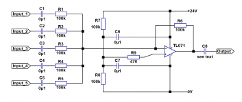
Here is a simple mixer which accomplishes what I think you want to achieve. It runs off the 24V wall wart power supply you suggest and has unity gain. As noise is not a consideration here, I have made the summing resistors quite high in value so that the necessary AC coupling capacitors C1-C5 can be quite small. With the values shown the -3dB point is 16Hz. Cheapo small ceramic capacitors would be fine here.
The op-amp should preferably be an FET input unity gain stable type - I suggest a TL071. C6 and C7 should be physically close to the supply pins on the i.c. (The diya cognoscenti will point out that C6 is superfluous, but I have included it to decouple the op amp +ve supply pin.)
C8 might not be necessary depending on the DC conditions that follow the output, but it won't hurt to include it. If the following power amp has a DC blocking capacitor at its input, omit C8. Otherwise its value depends on the input resistance R of the following power amp. The -3dB point is at a frequency f=1/(2.pi.R.C).
A capacitor Cx (not shown on schematic) in parallel with the feedback resistor R6 will create a first order low pass filter with frequency f=1/(2.pi.R6.Cx).
The whole thing will be quite happy on a small piece of stripboard as long as you stick to through-hole components (including the i.c.).
Attachments
If the audio source is a PC why don’t you mix down to mono in software?
Because I still want to use the surround audio signals with my speaker system.
Here is a simple mixer which accomplishes what I think you want to achieve.
Wow, thanks very much!
Just so I am sure I understand, the C6/R7 and C7/R8 are to create a "virtual ground" for the op amp that wants a dual-supply (i.e. +/-12V) Correct?
That's correct - and some would call it bias.
Just so I am sure I understand, the C6/R7 and C7/R8 are to create a "virtual ground" for the op amp that wants a dual-supply (i.e. +/-12V) Correct?
That's correct - and some would call it bias.
Here is a simple mixer which accomplishes what I think you want to achieve. It runs off the 24V wall wart power supply you suggest and has unity gain. As noise is not a consideration here, I have made the summing resistors quite high in value so that the necessary AC coupling capacitors C1-C5 can be quite small. With the values shown the -3dB point is 16Hz. Cheapo small ceramic capacitors would be fine here.
The op-amp should preferably be an FET input unity gain stable type - I suggest a TL071. C6 and C7 should be physically close to the supply pins on the i.c. (The diya cognoscenti will point out that C6 is superfluous, but I have included it to decouple the op amp +ve supply pin.)
C8 might not be necessary depending on the DC conditions that follow the output, but it won't hurt to include it. If the following power amp has a DC blocking capacitor at its input, omit C8. Otherwise its value depends on the input resistance R of the following power amp. The -3dB point is at a frequency f=1/(2.pi.R.C).
A capacitor Cx (not shown on schematic) in parallel with the feedback resistor R6 will create a first order low pass filter with frequency f=1/(2.pi.R6.Cx).
The whole thing will be quite happy on a small piece of stripboard as long as you stick to through-hole components (including the i.c.).
Hey , i am trying to build a 4 mono input to 1 mono output summing op amp mixer. But i am having noise problem. It is really messy. How to fix it? It is all basic circuit. I
Its virtual ground if it used as the ground for other parts of the circuit, its bias if it sets the operating point of a non-linear device. Fairly clear distinction.That's correct - and some would call it bias.
Hey , i am trying to build a 4 mono input to 1 mono output summing op amp mixer. But i am having noise problem. It is really messy. How to fix it? It is all basic circuit. I
Hello. I have seen your thread where you describe your difficulties with making a simple mixer. We need to check your circuit. Could you post the circuit as a first step?

Here it is the basic circuit. Tried yo implement the power supply entry, it is converted from dc. I am new to circuits. Trying to learn
") i tried this and around those basic circuits around the web. There is always noise. Even if it is small but still really audible.
i tried this and around those basic circuits around the web. There is always noise. Even if it is small but still really audible. And also when i check on oscilloscope i see spikes on the signal when it is steady.
Hello. I have seen your thread where you describe your difficulties with making a simple mixer. We need to check your circuit. Could you post the circuit as a first step?
Is it a Power problem?
Is it a Power problem?
I have to do a few hours school work with my grandson - a penalty of the lockdown - but will get back to you this evening or tomorrow. There is a lot wrong with the circuit!
I have to do a few hours school work with my grandson - a penalty of the lockdown - but will get back to you this evening or tomorrow. There is a lot wrong with the circuit!
Thanks for that info , I did think so as well about the circuit
)Waiting for your reply.
Hello hknatm
Looking at your circuit, the first question that arises is: do you expect the circuit to be able to drive a normal 8 or 16 ohm loudspeaker? This would be a definite no-no for the TL072, which cannot provide anything like enough current for this. If, by "speaker" you mean powered speakers such as computer speakers or active monitors, then the TL072 would be fine.
The 100 ohm resistor on the output is a good idea as long as the load is a sufficiently high impedance as it decouples the output from capacitive loads.
The biggest issue is the 2.2 ohm feedback resistor. Do you really mean 2.2 ohm, or did you intend 2.2k ohm?
With R1-R4 = 2.2k ohm, the maximum gain with a 2.2 ohm feedback resistor (which incidentally loads the output far too much) is only 1/1000, i.e. each signal input would be attenuated by 60dB. If, on the other hand, the feedback resistor is 2.2k ohm, then the maximum gain on any input is unity, x1.
Creating a virtual earth as you have done in your power supply is OK, but in my opinion it is probably better to make the negative side of your power supply the circuit common or ground, and create a mid-point bias point for the i.c. Whichever way you go, you really need DC blocking capacitors at all inputs and outputs.
You don't say on your circuit what the resistance of the potentiometers is. I think 10k pots were mentioned in the other thread.
In any event, R1-R4 really need to be substantially larger than 2.2k, I suggest 100k ohm. For unity max gain, the feedback resistor would also be 100k. You don't have to worry about the noise contribution of 100k at line level given the tiny input currents of a JFET input op amp.
With all these points (and others) in mind, you arrive at something like the attached circuit. With C1-C4 = 1uF, the nominal corner frequency of the low freq. roll-off is 16Hz. They could be larger, as could C5, if you wish.
The maximum gain on any input is unity. If you need more gain, just increase R5. For example, if R5=330k the gain is 3.3 or 10dB.
The second op amp in the TL072 is stabilised rather than left floating with inputs open circuit.
The power supply has been re-arranged so that a bias voltage for the op amps is generated rather than a virtual earth.
Have a look and ask if you have any questions about it. If you try it and your problems persist, we will need to look at the power supply and layout.
Have fun...
Last edited:
- Status
- This old topic is closed. If you want to reopen this topic, contact a moderator using the "Report Post" button.
- Home
- Source & Line
- Analog Line Level
- Need advice for a summing amp