Anyone explain this. Using a first order LP filter winisd/ Xsim correctly show the group delay ramping evenly up as frequency decreases.
When "connected" to a real driver, even when it's impedance is flattened with a series notch network to provide a virtually flat impedance and no more than +/- 5 degrees phase variation at the original Fs, the group delay rises to a peak and then falls as the frequency decreases?!
Observations?
When "connected" to a real driver, even when it's impedance is flattened with a series notch network to provide a virtually flat impedance and no more than +/- 5 degrees phase variation at the original Fs, the group delay rises to a peak and then falls as the frequency decreases?!
Observations?
Hi Nelsen, thanks for the reply. What baffled me is how a first order lp filter (created in winisd, say, and at line level therefore ) has an increasing gd with decreasing frequency and this rise increases at an even rate, whereas a choke/inductor selected for the same crossover point, the gd rises to a peak before dropping rapidly at Lf.
I need to investigate further....!
I need to investigate further....!
What baffled me is how a first order lp filter has an increasing gd
with decreasing frequency and this rise increases at an even rate.
The low pass filter group delay does approach 1/(2Pi x fo) seconds
at low frequencies, where fo is the corner frequency in Hz.
This is because the phase response, having the form of an arctangent function,
has a maximum slope at f=0Hz. This causes the group delay, being
the negative derivative of the phase, to reach a maximum peak at 0Hz.
For frequencies << fo, the phase response is nearly linear since arctan(x) ~ x for small x.
In that region there is nearly a constant delay (near the peak of the group delay curve).
Last edited:
Thanks....but for a first order value choke (180hz, -3dB point ) the gd peaks around 80 -100Hz before dropping again? Simulated in Xsim....with a series notch filter to level the driver impedance and flatten phase. True, a simulated first order "line level" filter in winISD does indeed perform as you state. And this is what is confusing me!!
for a first order value choke (180hz, -3dB point ) the gd peaks around 80 -100Hz
before dropping again? Simulated in Xsim....with a series notch filter to level the driver
impedance and flatten phase.
Can you post the complete circuit that does this?
Last edited:
Hi rayma,
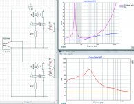
Yes, happy to post the circuit. As you can see the GD peaks then drops off. When modelled as a line level first order filter (in WinISD), the GD "gradient" remains linear.
You will note the RCL network is successful in flattening the impedance at driver resonance and with the zobel actually remains very flat up to around 10kHz where there is a small rise.
Observations very welcome!
Attachments
When modelled as a line level first order filter, the GD "gradient" remains linear.
Do you mean when modeled as a simple LR low pass filter?
If so, can you extend the plot of the group delay for that LR circuit
down to a very low frequency, like 0.1Hz? It should start to level out.
Rayma, thanks. Been very helpful....cheers.
Here is a plot of a first order low pass filter. It's an RC type, but it has the
same curves as an LR type does with the same time constant (where RC = L/R).
See the top set of curves, which are for a first order low pass filter.
The group delay increases at lower frequencies, leveling out eventually
to having a nearly constant group delay value approaching 0Hz.
https://i.stack.imgur.com/4pm1R.jpg
Last edited:
Now if we can just get Capt Grog to clear out some PM Space.
Thanks for reminding me, I was at 96% full, and managed to clear out some.
- Status
- This old topic is closed. If you want to reopen this topic, contact a moderator using the "Report Post" button.
- Home
- Source & Line
- Analog Line Level
- Delays created by first order crossover component.