Hello,
I plan to modify op-amp in my Zapco ASP-X4 Active Crossover.
As a newbie, I try to figure out which op-amp on the PCB function as the Input Op-Amp and which op-amp on the PCB function as Signal Path op-amp.
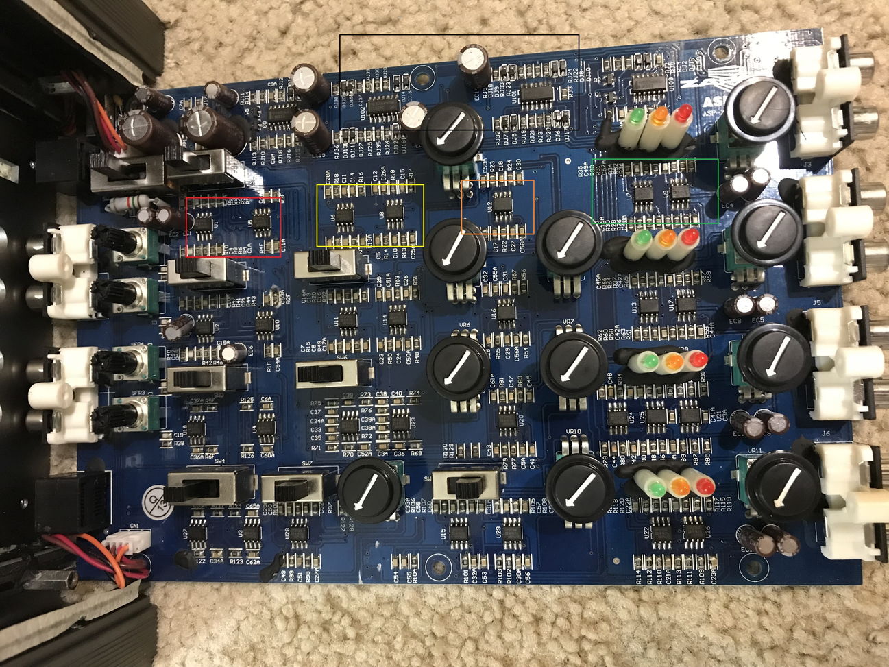
On the image below you can see that the input RCA is on the left side of the PCB (2 pairs of RCA for Front and Rear Stereo RCA input), while the output is on the right side of the PCB (4 pairs of RCA).
All the op-amp inside the red, yellow, orange and green rectangular mark are OP275, but from my limited understanding, some of the OP275 works as the op-amp for input stages while the rest function as signal path stages.
I plan to replace the OP275 at the input stages with LME49720 due to their super low noise and THD,
while for the OP275 used in the signal path, I plan to replace them with MUSES01.
I am guessing that the two op-amp inside the red rectangular mark is the op-amp for input stages, is this correct?
While the remaining op-amp inside the yellow, orange and green rectangular mark are the op-amp used in the signal path, is my guess correct?
Last, there are two more QUAD op-amps located at the top of the PCB (mark with black rectangular mark), they are TL074, can anybody please help me and let me know what the function of this TL074 op-amp?
I plan to replace this TL074 with OPA1644.
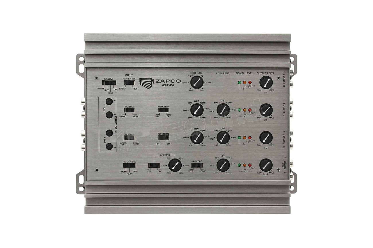
Below is the picture of the outside of the Zapco ASP-X4 so you can see the function of the potentiometer and switch on the PCB.
Thank You in advance
I plan to modify op-amp in my Zapco ASP-X4 Active Crossover.
As a newbie, I try to figure out which op-amp on the PCB function as the Input Op-Amp and which op-amp on the PCB function as Signal Path op-amp.
On the image below you can see that the input RCA is on the left side of the PCB (2 pairs of RCA for Front and Rear Stereo RCA input), while the output is on the right side of the PCB (4 pairs of RCA).
All the op-amp inside the red, yellow, orange and green rectangular mark are OP275, but from my limited understanding, some of the OP275 works as the op-amp for input stages while the rest function as signal path stages.
I plan to replace the OP275 at the input stages with LME49720 due to their super low noise and THD,
while for the OP275 used in the signal path, I plan to replace them with MUSES01.
I am guessing that the two op-amp inside the red rectangular mark is the op-amp for input stages, is this correct?
While the remaining op-amp inside the yellow, orange and green rectangular mark are the op-amp used in the signal path, is my guess correct?
Last, there are two more QUAD op-amps located at the top of the PCB (mark with black rectangular mark), they are TL074, can anybody please help me and let me know what the function of this TL074 op-amp?
I plan to replace this TL074 with OPA1644.
Below is the picture of the outside of the Zapco ASP-X4 so you can see the function of the potentiometer and switch on the PCB.
Thank You in advance
Last edited:
some of the OP275 works as the op-amp for input stages while the rest function as signal path stages.
The proper terminology is 'input buffer'. It is important because the whole signal pass through this op-amp and it defines the input impedance of the system.
The quad op-amps (TL074) are most probably for clipping indicator, so no need expensive parts there.
The all others ARE in signal path! If you use all features of the device (e.g. 4-way or 3-way with rear output) then all op-amps will be used. To replace them all will be very expensive!
If you don't use the full features then you need to identify which op-amps will be used. The top row you have marked is probably for HF and it is probably the most critical path where you want to use low noise, wide bandwidth and fast slew rate op-amps.
With the many cascaded op-amps for the band pass filters, I don't know whether upgrading them will be economical.
The bottom row is probably for LF where you may want to pay other attentions.
In summary, imo, what such xo device can do, doesn't worth the extra expensive upgrade you may want to do. But if you have no better options then you can try with step by step upgrade.
Hello Johnego,
Thank You for your very informative reply. I appreciate it.
By the way, I had decided to replace 14 pieces of OP275 op-amp (out of 29 pieces total with MUSES01 op-amp.
This 14 pieces are in the signal path of both the first high pass channel and second bandpass channel. (I only have 2 way active Dynaudio Esotar speaker for my front channel and I do not use rear channel).
This way I save cost by not upgrading all the op-amp.
14 pieces of MUSES01 will still cost me a lot, but at least not as bad as 29 pieces of MUSES01

I also already received 2 pieces of OP1644 op-amp to replace the TL074...
I understand as you point out that it might be just for clipping indicator, but I don't want to risk any chances and just upgrade everything at once...
From The spec, I see that OP275 is a Hybrid Bi-Polar/JFET op-amp design,
I hope the MUSES01 JFET design will not be a problem,
beside I don't really want to mix and match with MUSES02 because I read everywhere that MUSES02 soundstage is not as good as MUSES01, and I really want to upgrade the soundstage in my car
Thanks again
- Status
- This old topic is closed. If you want to reopen this topic, contact a moderator using the "Report Post" button.