Hello everyone,
I'm trying to learn amplifier circuits due to their awesomeness, but on my every attempt to create them, I'm encountering with different issues.
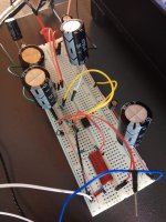
This time, I was trying to build a simple non-inverting OP-AMP amplifier with 4 times gain on a breadboard. I used a 24V switching supply(I don't have anything else), separated it to 12V Vcc+ and -, and I put two 10000uf caps for filtering. I don't have any decoupling capacitors yet but I'm planning to put 0.01uf, 0.1uf and 1uf ceramic caps parallel, close to the OP-AMP to the final and permanent circuit.
Everything is working fine. Except for two main issues.
First one, the output oscillates at 330, 750, 1100, 1500 hertz constantly. How can I prevent this? The buzzing and hissing caused by this is very annoying.
The second issue I'm having is the ground. When the amplifier isn't connected to the source, it's oscillating at 20hz if I'm not wrong. Normally this isn't an issue. Because when I connect it to a source it completely disappears. But the thing is, it oscillates at a very high volume and I think it may damage headphones or most likely IEMs.
This issue 'almost' completely disappears when I connect the ground to the power socket's earth. Is there another way? Because, you know, portable devices doesn't have any earth connection. How do they achieve this? What causes this? How can I understand what's happening?
Thank you, at least for reading until this point. Any opinion is appreciated.
I'm trying to learn amplifier circuits due to their awesomeness, but on my every attempt to create them, I'm encountering with different issues.
This time, I was trying to build a simple non-inverting OP-AMP amplifier with 4 times gain on a breadboard. I used a 24V switching supply(I don't have anything else), separated it to 12V Vcc+ and -, and I put two 10000uf caps for filtering. I don't have any decoupling capacitors yet but I'm planning to put 0.01uf, 0.1uf and 1uf ceramic caps parallel, close to the OP-AMP to the final and permanent circuit.
Everything is working fine. Except for two main issues.
First one, the output oscillates at 330, 750, 1100, 1500 hertz constantly. How can I prevent this? The buzzing and hissing caused by this is very annoying.
The second issue I'm having is the ground. When the amplifier isn't connected to the source, it's oscillating at 20hz if I'm not wrong. Normally this isn't an issue. Because when I connect it to a source it completely disappears. But the thing is, it oscillates at a very high volume and I think it may damage headphones or most likely IEMs.
This issue 'almost' completely disappears when I connect the ground to the power socket's earth. Is there another way? Because, you know, portable devices doesn't have any earth connection. How do they achieve this? What causes this? How can I understand what's happening?
Thank you, at least for reading until this point. Any opinion is appreciated.
We would really need to see your circuit diagrams to see just how you are trying to build this.
Even a relatively noisy SMPS should not actually cause any problems. How you achieve the 'virtual ground' from a single rail supply is also important. You need more than just two caps. Also, addig massive caps (10,000uF) to an SMPS may not be such a good move. The noise is high frequency and the supply regulation will be 'fast'. Something nearer 100uF or even less could well be better.
Even a relatively noisy SMPS should not actually cause any problems. How you achieve the 'virtual ground' from a single rail supply is also important. You need more than just two caps. Also, addig massive caps (10,000uF) to an SMPS may not be such a good move. The noise is high frequency and the supply regulation will be 'fast'. Something nearer 100uF or even less could well be better.
We would really need to see your circuit diagrams to see just how you are trying to build this.
Even a relatively noisy SMPS should not actually cause any problems. How you achieve the 'virtual ground' from a single rail supply is also important. You need more than just two caps. Also, addig massive caps (10,000uF) to an SMPS may not be such a good move. The noise is high frequency and the supply regulation will be 'fast'. Something nearer 100uF or even less could well be better.
Thank you for the reply.
")
I added 220uf and 10uf. It didn't do much but there is a little change in the tone. So, this seems to be the right path.
I roughly drew the circuit. Attached it.
Attachments
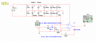
No, you have not "separated" it into + and -. You simply have a 24V supply applied to a circuit which requires a +12 and -12 supply.ArasU said:I used a 24V switching supply(I don't have anything else), separated it to 12V Vcc+ and -
For such initial experiments it might be best to use the slowest opamp you can find. Then you are less likely to have to worry about HF stability (e.g. due to long wires). In days of old people would use a 741.
He has created a virtual ground by means of R6 and R7 and so the circuit should work OK.
One thing to check... make sure that the 0V of the SMPS does not from a ground loop with any other equipment you connect to the circuit.
Ideally you want a power supply that is double insulated and that does not have mains earth carried through to the 0 volt line. If that situation happens then any other equipment that is similarly grounded will in fact short the lower half of your virtual ground out when you come to connect it. Does that make sense ?
That virtual ground isn't the best, but should be OK for testing.
I built a cheap, quick and dirty preamp designed to be powered from a laptop supply. The board is very small and crammed into a small router enclosure. I used TLE2426 to establish the virtual ground. I also used an R-L-C filter for the power supply. I got the inductors out of computer power supplies. I put an inductor in both legs of the power supply. I added an extra R-C filter to the input of the 2426.
The preamp works great. It's not as quiet as one built with a proper split supply and metal film resistors, but I built it just as an exercise. I wanted to see if I could build practical line level circuits that run off a laptop or other switching supply, and I did. I also built a headphone amp using the same strategy, with metal film resistors, and it works great.
Finally, you have to have a ceramic bypass cap close to the chip. I solder mine on the bottom of the board, directly to the chip's pins.
He has created a virtual ground by means of R6 and R7 and so the circuit should work OK.
One thing to check... make sure that the 0V of the SMPS does not from a ground loop with any other equipment you connect to the circuit.
Ideally you want a power supply that is double insulated and that does not have mains earth carried through to the 0 volt line. If that situation happens then any other equipment that is similarly grounded will in fact short the lower half of your virtual ground out when you come to connect it. Does that make sense ?
When I touch to the SMPS's heatsink, the tone of the buzz changes. That might be the issue. Hmm.
I did everything from beginning on the breadboard in case of a missed ground loop or any mistake. There was no change.
So, I removed everything except 220uf from both sides. The tone changed but the buzz remained the same.
I tried different combinations. The best one was putting 10uf to the negative rail and putting 220uf to the positive one. When they taught filtering, they say "put everything you have!". So, that's not the case then. But I really don't understand what's going on. Why would this happen? So weird...

To take the set up you have further and to see what is wrong is going to require an oscilloscope and a few quick measurements. We would look at the opamp output and the rails to see what was going on.
What type of power supply is your 24 volt switching one ? Most laptop type supplies will produce a clean output.
If you haven't an oscilloscope then I would suggest using a 9 volt battery in place of the SMPS and confirming the circuit works as expected. Check the DC voltage of the rails are correct at approximately +4.5 and -4.5 volts and that the output pin of the opamp is at zero volts. If those voltages are not correct then you have a basic error in the construction somewhere or a faulty (fake) opamp.
(the 741 opamp DF96 mentioned would be a good choice for experimenting with... remember it is a 'single' with different pinouts though)
Basic circuit like yours, the possibility that cause oscillation are:
1. No decoupling capacitor.
Please add decoupling capacitor as close as possible to pin power of the op-amp.
2. Bad layout, ex. long trace of feedback resistor.
If you can not make that trace as short as possible, please add capacitor parallel with feedback resistor. The value of capacitor around 10pF - 100pf depend the value of feedback resistor. Place the capacitor as close as possible to op-amp.
3. Capacitive loading. Maybe you have long cable at output.
Please add 33 Ohm - 100 Ohm resistor at output of the op-amp.
To take the set up you have further and to see what is wrong is going to require an oscilloscope and a few quick measurements. We would look at the opamp output and the rails to see what was going on.
What type of power supply is your 24 volt switching one ? Most laptop type supplies will produce a clean output.
If you haven't an oscilloscope then I would suggest using a 9 volt battery in place of the SMPS and confirming the circuit works as expected. Check the DC voltage of the rails are correct at approximately +4.5 and -4.5 volts and that the output pin of the opamp is at zero volts. If those voltages are not correct then you have a basic error in the construction somewhere or a faulty (fake) opamp.
(the 741 opamp DF96 mentioned would be a good choice for experimenting with... remember it is a 'single' with different pinouts though)
And one further thought... some SMPS behave strangely when very lightly loaded, perhaps going into a 'burst' or power saving mode.
I changed the parts, tried with different OP-AMP models. (I don't have a 741 unfortunately)
Didn't do much difference.
Then I found two 12V adaptors lying around. Old types. Removed the resistor division and made a classic two battery Vcc + and -. The tone changed but hiss and buzz was still there.
I'm using my computer as an Oscilloscope. There's a program called Winscope. It reads from the line input of the computer. It's not that good, but it works.
When a correctly wired circuit behaves strangely then high frequency oscillation should be suspected. This can show itself as hum, distortion, low frequency oscillation etc. A breadboard layout with long wires is asking for trouble with modern fast chips.
So, I should put some ceramic decoupling capacitors very near to the OP-AMP. They didn't arrive yet. I hope the problem is that easy. I was very eager to learn amplifiers. It's been a disappointment until this point. I thought I could build something Hi-Fi for myself, yet I was unable to build something simple that works properly without damaging headphones, buzzing and hissing constantly.
Weird thing happened though. I think I'm hearing Greek. Very subtle. It's picking up radio frequencies as well. The closest Greek speaking country is Cyprus. 250-300 kilometres away.
That virtual ground isn't the best, but should be OK for testing.
I built a cheap, quick and dirty preamp designed to be powered from a laptop supply. The board is very small and crammed into a small router enclosure. I used TLE2426 to establish the virtual ground. I also used an R-L-C filter for the power supply. I got the inductors out of computer power supplies. I put an inductor in both legs of the power supply. I added an extra R-C filter to the input of the 2426.
The preamp works great. It's not as quiet as one built with a proper split supply and metal film resistors, but I built it just as an exercise. I wanted to see if I could build practical line level circuits that run off a laptop or other switching supply, and I did. I also built a headphone amp using the same strategy, with metal film resistors, and it works great.
Finally, you have to have a ceramic bypass cap close to the chip. I solder mine on the bottom of the board, directly to the chip's pins.
I thought TLE2426 had a very limited current limit. I don't know. With a preamp, it may work fine, but my main goal is building an amplifier with a 7x gain. I'm going to use an OP-AMP with an Class AB amplifier. Funny part is, I can't even get an OP-AMP to work properly, without any problems.
Those are all good suggestions from bimo and it is worth trying a small cap across the feedback resistor.
Do you get the noise with the audio input shorted ?
If it is still not working correctly then I would suggest pulling all the components from the breadboard and starting again. Its only five minutes work to build it up again.
Do you get the noise with the audio input shorted ?
If it is still not working correctly then I would suggest pulling all the components from the breadboard and starting again. Its only five minutes work to build it up again.
Basic circuit like yours, the possibility that cause oscillation are:
1. No decoupling capacitor.
Please add decoupling capacitor as close as possible to pin power of the op-amp.
2. Bad layout, ex. long trace of feedback resistor.
If you can not make that trace as short as possible, please add capacitor parallel with feedback resistor. The value of capacitor around 10pF - 100pf depend the value of feedback resistor. Place the capacitor as close as possible to op-amp.
3. Capacitive loading. Maybe you have long cable at output.
Please add 33 Ohm - 100 Ohm resistor at output of the op-amp.
1) I'm going to put decoupling caps when they arrive. 0.01uf, 0.1uf and 1uf ceramic capacitors. Very close to the IC. I hope they make a change.
2) I just trimmed the components and put everything very close to each other. The background noise noticeable decreased. Hmm. I was planning to put two modes to the final circuit with a switch. 4x and 8x gain. (75K / 10K - 33K / 10K) And I have to make it a long wire -to the feedback resistor- to achieve that. So I shouldn't do that. That's bad.
3) 5 cm long, maybe.
I tried to add a resistor. Didn't do much. But, if I add a resistor at the output it'll change the output impedance and cause a voltage divider. Or will it? Hmm. I don't know...

A low value series resistor at the output is good practice. Something like 47 or 100 ohm. It has negligible effect on output voltage assuming you connect this to another line input stage.
Long wires will pick up interference, particularly if you are surrounded by equipment that radiates a lot of interference.
Long wires will pick up interference, particularly if you are surrounded by equipment that radiates a lot of interference.
My less knowledgeable reply
I would lower the input LPF frequency (I can't make out any values to determine Fc) make it 150kHz at a guess, maybe lower.
Second suggestion is to add a low value cap across the feedback resistor. Perhaps 5pF to 33pF. Determine empirically using a scope.
Echo Mooleys advice to add a series resistor to the output of 47-100R
Lastly, as I have done this many times....
Check you haven't accidentally used a resistor that is e.g. 10 times the value intended. I made mistakes all too often when resistor colour codes changed from 4 to 5 band coding, and still do occasionally. Now I always double check the values with a DMM before I power anything up.
Or...an open circuit feedback path...
That's my (novice) advice.
Last edited:
But, if I add a resistor at the output it'll change the output impedance and cause a voltage divider. Or will it? Hmm. I don't know...
If you use a 47 ohm resistor and you are driving a 47K input impedance (industry standard but don't take it for granted), then the attenuation introduced is 0.1 %. It is completely negligible. Even at 4.7K, it is only 1%.
But if you look at the output as an input (which you must consider if driving reactive loads or long leads), then the 47 ohm resistor greatly attenuates any signal trying to enter the output node. That's because the output impedance of an op amp is very low, much less than 1 ohm with feedback applied. So even if output impedance is 0.47 ohms (it will typically be much lower), then attenuation of any unwanted signal will be 99%.
It's a win-win. Negligible penalty and tremendous benefit. Just one resistor.
Put it as close to the output pin of the chip as possible, to maximize effect.
Last edited:
- Status
- This old topic is closed. If you want to reopen this topic, contact a moderator using the "Report Post" button.
- Home
- Source & Line
- Analog Line Level
- PSU and OP-AMP Caused Oscillation?