OPA2134 is a dual opamp. You should take care of unused half, that is short the ouput an minus input and connect the plus input to the virtual ground.
It shorted and acted weird, but I was think about putting the same wires as the other side. So I could get a better THD.
If you use a 47 ohm resistor and you are driving a 47K input impedance (industry standard but don't take it for granted), then the attenuation introduced is 0.1 %. It is completely negligible. Even at 4.7K, it is only 1%.
But if you look at the output as an input (which you must consider if driving reactive loads or long leads), then the 47 ohm resistor greatly attenuates any signal trying to enter the output node. That's because the output impedance of an op amp is very low, much less than 1 ohm with feedback applied. So even if output impedance is 0.47 ohms (it will typically be much lower), then attenuation of any unwanted signal will be 99%.
It's a win-win. Negligible penalty and tremendous benefit. Just one resistor.
Put it as close to the output pin of the chip as possible, to maximize effect.
I would lower the input LPF frequency (I can't make out any values to determine Fc) make it 150kHz at a guess, maybe lower.
Second suggestion is to add a low value cap across the feedback resistor. Perhaps 5pF to 33pF. Determine empirically using a scope.
Echo Mooleys advice to add a series resistor to the output of 47-100R
Lastly, as I have done this many times....
Check you haven't accidentally used a resistor that is e.g. 10 times the value intended. I made mistakes all too often when resistor colour codes changed from 4 to 5 band coding, and still do occasionally. Now I always double check the values with a DMM before I power anything up.
Or...an open circuit feedback path...
That's my (novice) advice.
A low value series resistor at the output is good practice. Something like 47 or 100 ohm. It has negligible effect on output voltage assuming you connect this to another line input stage.
Long wires will pick up interference, particularly if you are surrounded by equipment that radiates a lot of interference.
So I can put a resistor, if the output is going into another high impedance input, low impedance output stage ...like a Class AB amplifier which I was thinking about putting.
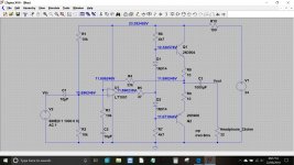
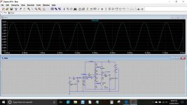
I was also experimenting about a Class AB amplifier. I was planning to put at the end of the OP-AMP. And it works great on SPICE programs. BD139 and BD140 are getting 500mW and that's fine even without a heatsink.
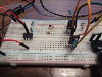
I just tried to build it. Transistors exploded. Literally. Instantly. They're melted. I'm shocked.

Do you have any idea about what just happened? The parts were fine. I'm sure, I test them before putting.
Attachments
Always try and use a current limited power supply. If you are really interested in all this then you need a variable power supply with variable current limiting.
What happened to you is common when powering up a design for the first time. Assuming all the parts were fitted correctly then I suspect your two diodes are providing to high a forward bias voltage. You should have emitter resistors fitted to each BD transistor, say 10 ohms to begin with.
What happened to you is common when powering up a design for the first time. Assuming all the parts were fitted correctly then I suspect your two diodes are providing to high a forward bias voltage. You should have emitter resistors fitted to each BD transistor, say 10 ohms to begin with.
I added it to my list. I'm slowly gathering the tools. They're kinda expensive considering the exchange rate in my country.
So, I put two 10 ohm resistors to the emitters. You know, for two transistors. They burned. Literally. There was fire. It was fun.
Maybe I should try 33 ohms. But won't it increase the output impedance? Because it goes to the headphones after this point. There's nothing next.
Or maybe I should try something like 2N3904 and 2N3906. I really don't know.
Something must be wrong with the construction because 10 ohms would definitely limit the available bias voltage to the transistors.
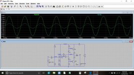
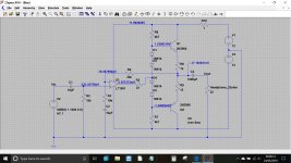
Try this. Build it exactly as shown (which is a single rail design). Remember to add a decoupling cap across the opamp supply pins.
The 100 ohm in series with the supply is to help prevent damage if you do something wrong. The circuit should work OK with that resistor in place and allow you to test that the DC voltages are correct. If it all seems OK then reduce or link out the test resistor.
None of the values are critical but obviously keep like for like pairs of resistors at the same values.
Attachments
Something must be wrong with the construction because 10 ohms would definitely limit the available bias voltage to the transistors.
Try this. Build it exactly as shown (which is a single rail design). Remember to add a decoupling cap across the opamp supply pins.
The 100 ohm in series with the supply is to help prevent damage if you do something wrong. The circuit should work OK with that resistor in place and allow you to test that the DC voltages are correct. If it all seems OK then reduce or link out the test resistor.
None of the values are critical but obviously keep like for like pairs of resistors at the same values.
I built it. It worked very similarly but I'm not a fan of putting electrolytic capacitors to the signal path. I wasn't expecting a breadboard circuit to sound amazing but they degraded the sound quite a bit to be honest, compared to the other designs. 'Bloated' is the right term I guess. And as a note, the background hiss and buzz were still audible as before.
After I tried your circuit, I built mine again. It didn't burn. It sounded well except for the background hiss I was talking about earlier. Few hours later I tried it again. The resistors and the transistor burned instantly. So weird...
I'm kinda tired of burning transistors and resistors. I got a pile of dead components.
I don't think this'll work. Is this the only way to drive power hungry headphones? Is there another way? I thought about limiting the current with a 2 transistor current limiting circuit, but Class AB section may 'absorb' the current and this'll be bad for the OP-AMP. So, I don't know. I don't even know if that's the issue or it can be solved like that. Limiting the current may clip the signal as well.
People who are afraid of using coupling capacitors often have to use more complex less reliable circuitry to achieve a similar result.
If your circuits are burning components then something is wrong, either with the circuit or your construction of it. Note that to successfully build a circuit it is necessary to make sure that each thing connects to what it should connect to and nothing else - but this is not sufficient as you also need to get the connections right (e.g. right order of grounding, low stray capacitance/inductance, low coupling between circuit loops etc.) It is easy to build a circuit which is both 'correct' and totally wrong!
Maybe you should try building and debugging a simpler circuit?
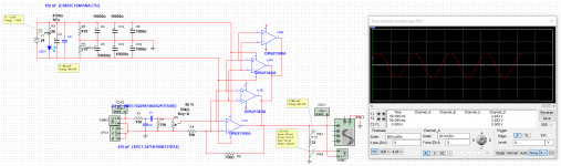
Simply paralleling opamps works great in simulation but is likely to fail in real life because no two opamps are identical so some will do most of the work while the others do almost nothing. To make it work they each need their own feedback arrangements and then you combine the outputs via ballast resistors.ArasU said:Maybe doing something like this.
People who are afraid of using coupling capacitors often have to use more complex less reliable circuitry to achieve a similar result.
If your circuits are burning components then something is wrong, either with the circuit or your construction of it. Note that to successfully build a circuit it is necessary to make sure that each thing connects to what it should connect to and nothing else - but this is not sufficient as you also need to get the connections right (e.g. right order of grounding, low stray capacitance/inductance, low coupling between circuit loops etc.) It is easy to build a circuit which is both 'correct' and totally wrong!
Maybe you should try building and debugging a simpler circuit?
I guess that's how people learn. I have 30-40 pairs of transistors left. They aren't expensive or anything. I can spare all of them to learn what I'm doing wrong. Parts are just hard to find in this country. I have to order from international sites. I tried to find decoupling capacitors today. I couldn't find any. When I asked why I was unable to find any, the guy who owns the place said "Why would we get capacitors that small, buy one of these." and he was pointing at a 0.5F super capacitor. I had to explain what decoupling is. He said that he is an Electrical Engineer. He didn't know anything about decoupling. Whatever.
I built it. It worked very similarly but I'm not a fan of putting electrolytic capacitors to the signal path. I wasn't expecting a breadboard circuit to sound amazing but they degraded the sound quite a bit to be honest, compared to the other designs. 'Bloated' is the right term I guess. And as a note, the background hiss and buzz were still audible as before.
After I tried your circuit, I built mine again. It didn't burn. It sounded well except for the background hiss I was talking about earlier. Few hours later I tried it again. The resistors and the transistor burned instantly. So weird...
I'm kinda tired of burning transistors and resistors. I got a pile of dead components.
I thought about limiting the current with a 2 transistor current limiting circuit, but Class AB section may 'absorb' the current and this'll be bad for the OP-AMP. So, I don't know. I don't even know if that's the issue or it can be solved like that. Limiting the current may clip the signal as well.
My circuit is stable because of the 10 ohm resistors, yours without them is not.
The circuit can be converted to dual rail very easily. Note the extra diodes added. These increase the bias voltage and reduce crossover distortion. The emitter resistors are now 15 ohm to reduce power dissipation in the transistors.
All the caps can be removed (as long as you are using a FET opamp) although I wouldn't advise that doing so is good practice.
Attachments
- Status
- This old topic is closed. If you want to reopen this topic, contact a moderator using the "Report Post" button.
- Home
- Source & Line
- Analog Line Level
- PSU and OP-AMP Caused Oscillation?