Hi,
I just bought a Copland CTA 301 in very good status.
The former owner replaced the line valves with a unreadable type and he also cut one resistor (one each channel).
Unfortunately he cannot provide me the original resistors neither their rresistance value.
Is there anyone who could pass me the list of components/service manual of CTA 301 ?
At least is there anyone who could tell me what is the value of resistors R32 (R132)?
Many thanks.
Attachments
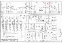
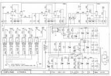
So this preamp doesn't work.Without that resistor, there's no plate voltage on the tube.
Also be very careful here. There is a high probability that schematic is not correct. Early on there was a change. The line section was changed from the SRPP that you see, to an anode follower direct coupled to a cathode follower.
If the schematic is correct then as kevinkr stated R31, and R32 should be the same. I believe it to be 332 ohms.
If the change has been implemented R32 should be 100k.
There are two ways to confirm. Locate R31 if it is 1k, then the missing resistor is probably 100k. If it is 332R, then the missing one is probably 332R also.
To double check this, with the power off and drained down, see if there is a connection from the upper part of R32 to pin 8 of the tube. If it is then the schematic is right. If there isn't a connection, check the upper part of R32 and pin 6. If they are connected, then the resistors are 100k and 1k.
Hi,
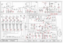
Copland Customer Service explained me that my Preamp was upgraded as for Copland retrofit.
Additional resistors are placed in the lower PCB face (I didn't notice them).
The new schematics is in attachment.
See you and many thanks for your help !!!
Copland Customer Service explained me that my Preamp was upgraded as for Copland retrofit.
Additional resistors are placed in the lower PCB face (I didn't notice them).
The new schematics is in attachment.
See you and many thanks for your help !!!
Attachments
So this preamp doesn't work.Without that resistor, there's no plate voltage on the tube.
Also be very careful here. There is a high probability that schematic is not correct. Early on there was a change. The line section was changed from the SRPP that you see, to an anode follower direct coupled to a cathode follower.
If the schematic is correct then as kevinkr stated R31, and R32 should be the same. I believe it to be 332 ohms.
If the change has been implemented R32 should be 100k.
There are two ways to confirm. Locate R31 if it is 1k, then the missing resistor is probably 100k. If it is 332R, then the missing one is probably 332R also.
To double check this, with the power off and drained down, see if there is a connection from the upper part of R32 to pin 8 of the tube. If it is then the schematic is right. If there isn't a connection, check the upper part of R32 and pin 6. If they are connected, then the resistors are 100k and 1k.
Hi Audiopro,
This is an MK 1 and then the tubes in the line-stage are ECC82 or equivalent ... correct?
If I am informed well the MK2 has ECC88 (or equivalent) but does it also has this change in output stage topology.
If I am correct this modified topology has a lower output impedance.
I want to buy one, modify it to a phono stage only. Bypass balance and volume, add a lundahl MC input transformer and also an output transformer from Lundahl with a 2:1 ratio lowering the gain with 6dB and making the output impedance 4x lower (or increase the load impedance by 4 the output stage sees) The transformer will feed XLR connectors as my phone amp will be sitting 4 meters from my pre-amp.
Cheers,
Peter
Hello Rick,
I attach here the files I spoken about.
Regards
Hi Scuro,
I put the resistor values that you added in the list in the schematic.
The resistors R20-R25 should be much higher, like in the 220k to 470k range as they are in parallel when you one of the inputs are selected and no signal will come trough. Maybe 460k?
Peter
Attachments
Hi PSchut,
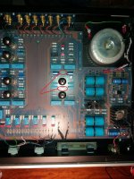
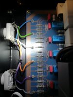
Your observation is right, but R20 values are right indeed.
I attach a picture I've just taken in order to show you R20 value.
Each RL has a set of 3 Resistors of 46R4.
I taken a measurement between input line (Eg. From R19) an ground, and the measured value is higher than 60k.
This means things are not working exactly as shown in the schematics, otherwise I should had measured the parallel of five 46R4.
The day I will disassemble again my Copland I will read the real circuit.
Bye
Attachments
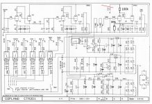
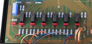
I have seen pictures where these resistors are actually different. (see attached pic)
One other note on the modification of the output stage.
There is a feedback resistor that connects the output (after the coupling caps) to the input grid of the first gain stage (of the line amp)
C16 to R30/V5
It must have been otherwise the line stage would have a gain of 100 or something. It now is about 5 times.
Cheers,
Attachments
Last edited:
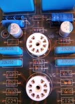
Hi, I was looking for information on the characteristics of the preamp's power LED and I came across this thread.
Unfortunately, when replacing all the capacitors of the pre - terrible axial Philips, out of specifications - I was left with the head of the LED in my hand...
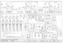
But coming to the subject of the thread, the resistors involved in the discussion have a value of 1.62K (I am attaching their photo).
I don't dream - of course - of making changes to the preamplifier but I'd be curious to know the reasons for the change proposed by Copland, by someone who knows more than me.
Thank you.
P.S.: how could I remedy the lack of information on the characteristics of the preamp led?
Unfortunately, when replacing all the capacitors of the pre - terrible axial Philips, out of specifications - I was left with the head of the LED in my hand...
But coming to the subject of the thread, the resistors involved in the discussion have a value of 1.62K (I am attaching their photo).
I don't dream - of course - of making changes to the preamplifier but I'd be curious to know the reasons for the change proposed by Copland, by someone who knows more than me.
Thank you.
P.S.: how could I remedy the lack of information on the characteristics of the preamp led?
Attachments
You mean, what to replace it with? Even though there are millions of type-numbers, LEDs are not complicated. Go by shape size and color.how could I remedy the lack of information on the characteristics of the preamp led?
- Home
- Source & Line
- Analog Line Level
- Copland CTA 301 missing Resistors