OK ")
So have you tried it, and does it work ? or is there some problem you need help with. My concerns were whether the circuit would bias up correctly as it may depend a lot on the type of FET used. The 21 volts across the 620 ohm is the critical figure. If that is way out then you need to alter the ratio of the 470 ohm and 1.2k.
Try it first and see what happens.
Yes, a multiplier can be used but you will need to ensure the caps are big enough.
Also, as haiqu mentioned earlier, you may find ripple from the power supply affecting the circuit.
You could perhaps sacrifice a bit of supply voltage and use a regulator such as the LM317AHV (high voltage LM317). Perhaps aim for 48 volts unregulated and a regulated 40 volt rail. That should give no hum at all.
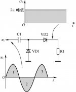
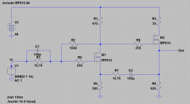
First I think the FET used is IRF610, as I don't see how this could work with p-channel transistor.
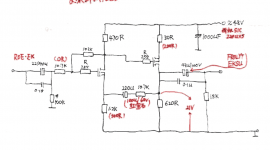
In the Triodizer article it is mentioned that for maintaining of the gain of the input FET constant at all frequencies, a capacitor parallel to the input resistor (in this case 107k) should be used. Since Cgd of IRF610 is 15 pF, shouldn't we put 15 pF * (107+102)/107 = 29.3 pF (closest available is 30 pF though) in parallel with 107k? Wouldn't it make more sense to make the two resistor the same, so that the gain is set to 2?
The part of the schematic I am not so sure about is the 102k in the input FET source and the 107k in series with 220 uF. At first glance I thought that it is used to set the overall gain to 1, as the values are similar to the ones regulating the gain of the input FET, but I don't see how does it work. Can anybody explain this?
Meanwhile I'll make a simulation of it and post results.
@ Mooly, you are right, with 102 and 107 it doesn't even work. With these values, C1 becomes 158 pF.
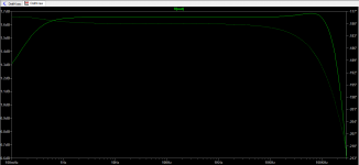
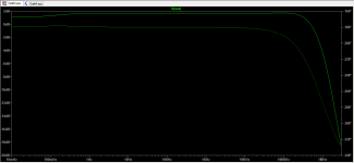
I substituted the source resistor with suggested (in red) 300R, as it gives better transfer function. The suggested 200R for drain of the output FET shuts it down, and the transfer function becomes -42 dB in the audio band.
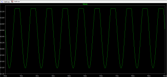
While the transfer function looks nice, the transient doesn't, as the output gets clipped (THD 16%). Please see attached. I guess the bias of the output FET is wrong, as the DC point for output FET source is 42V, not 21 as suggested in the schematic.
Any suggestions how to fix this?
I substituted the source resistor with suggested (in red) 300R, as it gives better transfer function. The suggested 200R for drain of the output FET shuts it down, and the transfer function becomes -42 dB in the audio band.
While the transfer function looks nice, the transient doesn't, as the output gets clipped (THD 16%). Please see attached. I guess the bias of the output FET is wrong, as the DC point for output FET source is 42V, not 21 as suggested in the schematic.
Any suggestions how to fix this?
Attachments
- Status
- This old topic is closed. If you want to reopen this topic, contact a moderator using the "Report Post" button.
- Home
- Source & Line
- Analog Line Level
- Help analyze the circuit