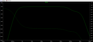
@Anti, you are absolutely correct. After adding 100k resistor there were no changes, but the capacitor made all the difference. Attached new schematic and transfer function. The bandwidth reduces when R5 is increased to 200, but it is still 500 kHz. Do you think that additional elements at the output, such as capacitors or inductors would be needed?
Attachments
Unfortunately the transient analysis shows that the circuit oscillate, see attached. Solution I have found in the simulation is to remove R7 and C2. With them removed, the circuit seems to work fine.
I didn't really understood why we have that feedback circuit, are we losing anything by removing it?
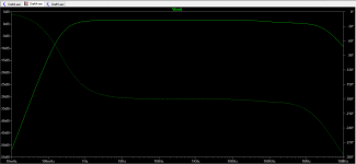
Second diagram is transient response without R7 and C2. Both are with output capacitor added to remove DC offset. The simulation shows THD 0.019.
Also attached transfer function without R7 and C2.
I didn't really understood why we have that feedback circuit, are we losing anything by removing it?
Second diagram is transient response without R7 and C2. Both are with output capacitor added to remove DC offset. The simulation shows THD 0.019.
Also attached transfer function without R7 and C2.
Attachments

Last edited:
Hi,
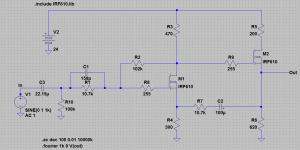
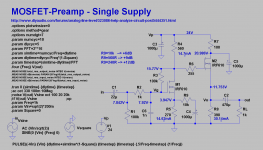
here´s a schematic that just might work")
Insted of feeding back from output to source I chose the RC-Network to select for the AC-gain and to go without global feedback.
THD still remains low enough and with a nice distribution of harmonics ... so a decent sound should be expectable.
Also I chose parts with common standard values.
Added a input filter cap that limits the bandwidth to ~110kHz ... though the circuit seems perfectly stable without it.
Also added a lytic from the Buffer´s drain to decouple and smooth the supply rail and to increase ouput voltage headroom.
With 1V In and +12dB gain the Buffer´s gate already becomes more positive than the Drain .... with associated THD increase.
One could of course increase the supply rails or omit with R7/C5 alltogether to gain more output headroom ... I actually don´t see the purpose behind the solitary Drain-R (R7) without a smoothing cap ... it just wastes precious headroom.
If the AC-gain resistor R9 is made switchable make sure to mute the output as it will give loud -possibly destructive- popping switching noise.
For the R9 values given here the gains are +6dB, +9dB and +12dB, which should fulfill almost all line level requirements.
Varying the Gate resistor R3 one can tune the bias currents and the DC-voltage level at the node Vo.
jauu
Calvin
ps. I would also add another 100k in front of C1 from in to gnd, just to be sure that C1 will be fully discharged if the Pre is connected to a source.
here´s a schematic that just might work
Insted of feeding back from output to source I chose the RC-Network to select for the AC-gain and to go without global feedback.
THD still remains low enough and with a nice distribution of harmonics ... so a decent sound should be expectable.
Also I chose parts with common standard values.
Added a input filter cap that limits the bandwidth to ~110kHz ... though the circuit seems perfectly stable without it.
Also added a lytic from the Buffer´s drain to decouple and smooth the supply rail and to increase ouput voltage headroom.
With 1V In and +12dB gain the Buffer´s gate already becomes more positive than the Drain .... with associated THD increase.
One could of course increase the supply rails or omit with R7/C5 alltogether to gain more output headroom ... I actually don´t see the purpose behind the solitary Drain-R (R7) without a smoothing cap ... it just wastes precious headroom.
If the AC-gain resistor R9 is made switchable make sure to mute the output as it will give loud -possibly destructive- popping switching noise.
For the R9 values given here the gains are +6dB, +9dB and +12dB, which should fulfill almost all line level requirements.
Varying the Gate resistor R3 one can tune the bias currents and the DC-voltage level at the node Vo.
jauu
Calvin
ps. I would also add another 100k in front of C1 from in to gnd, just to be sure that C1 will be fully discharged if the Pre is connected to a source.
Attachments
Last edited:
It would make more sense if the first fet's load resistor would be filtered (so a R7-C5 rc between the '+' rail and the R4).
Also, the C6 is "dangerously close" to the first fet gate. For the sake of stability, personally I would put it straight across the R1 (and thus avoid the need to add another gate-stopper). I would also up the R2 a bit, in original the ratio R2/R3 was 1/10. Gain would be best set with tweaking R9 as you already did.
Also, the C6 is "dangerously close" to the first fet gate. For the sake of stability, personally I would put it straight across the R1 (and thus avoid the need to add another gate-stopper). I would also up the R2 a bit, in original the ratio R2/R3 was 1/10. Gain would be best set with tweaking R9 as you already did.
Hi,
C6 is used to filter HF. As such it 'needs' the impedance of R2 to function as frequency depedent divider.
If conncted across R1 instead it simply presented a dead short to the source at higher frequencies.
Making R2 10k would mean a signal loss of roundabout -3dB, while the loss remains lower at ~-0.5dB with 1k.
If one feels uneasy with the cap right at the Gate of the MOSFET one could insert another small resistor or a ferrite bead.
jauu
Calvin
I was just about to ask about placing 255R between C6 and M1. I wasn’t aware that ferrite bead could be used. What would be the benefit compared to a resistor? I guess better prevention of oscillations at high frequencies.
Well done for bypassing the source resistor, it didn’t work well in my simulation with that oscillating feedback that I have eventually removed, but forgot to put it back
Well done for bypassing the source resistor, it didn’t work well in my simulation with that oscillating feedback that I have eventually removed, but forgot to put it back
- Status
- This old topic is closed. If you want to reopen this topic, contact a moderator using the "Report Post" button.
- Home
- Source & Line
- Analog Line Level
- Help analyze the circuit