It's been my experience that unless you're really doing something crazy, veroboard will work just fine. One of the best ways to get folks involved with resolving the issues you're seeing is to post the schematic that you're working from with a few pictures (top and bottom), to show everyone what your build looks like.
Dave
Dave
I have tried to build a basic low oise preamp using ne5532 but is suffers from well noise.
Post some photos of your build.
I built several NE5532 and NE5534 circuits on perfboard with no problems. Maybe Adason is correct, maybe the supply decoupling is too far away (or nonexistent), maybe you pick up some RF signal or maybe you have oscillations due to long input or output signal wires without some sort of damper or stopper resistor.
Anyway, like Dave and Rayma wrote, posting a schematic and photos would help to get better advice.
Anyway, like Dave and Rayma wrote, posting a schematic and photos would help to get better advice.
...It is very sensitive to rf and moving my had closer to the input capacitor increases the noise....
High-gain amplifiers MUST be in a metal box. Laying out in the open they DO suck-up all the hum, buzz, and Peruvian Radio in the air.
I made an 8-channel preamp I use in my truck, using 4 ne5532 packages, on stripboard, powered by a +/- 12v switching power supply I got on ebay. I can report the NE5532 misbehaves badly when it doesn't have proper decoupling capacitors on the power connections. Those capacitors are a must.
I've built filters, tone controls, and whole preamps on boards like this. SBB2805-1 Chip Quik Inc. | Prototyping, Fabrication Products | DigiKey You can cut the traces and even grind them off to get the board you want. You can come up with much better layouts than what's possible with veroboard. You can come up with great layouts with a little ingenuity; layouts that use a minimum of jumper wires. Putting parts on both sides of the board not only helps with layout challenges, but it saves space.
It's been pointed out several times that you have to have a 0.1 uF bypass capacitor as close to the chip as possible. I bought 100 of these C322C104M1U5TA KEMET | Capacitors | DigiKey and I solder them directly to the pins of the op amp on the bottom of the board. Every chip gets one.
Also on board electrolytic capacitors are required. You need to provide a schematic of your power supply and detail of your layout. These on board capacitors need to be close to the chips.
Grounding is paramount. All audio grounds need to be connected together and connected to power supply ground at one and only one point.
The 0.1 uF bypass capacitor can be a general purpose ceramic capacitor, or a film capacitor. Even the old fashioned ceramic "disc" capacitors work fine in this application. I have a collection similar to this GB100: Jameco Valuepro : 200 Piece Ceramic Disc Capacitor Grab Bag : Passive Components that I reach for all the time.
Last edited:
huddslad,
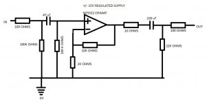
How do you have the power supply leads decoupled? They are not drawn on the schematic. Take a couple pics of the veroboard, both top and bottom and post them. That will make diagnosing the problem and assisting you much easier.
Dave
+1
Need to show decoupling and physical layout.
I'll argue that you only need a single 100n cap between the +/- voltages here but a cap from each rail to 0V will be fine too.
Depending on physical arrangement I'd likey also add 'bulk' decoupling with electrolytics or Tantalum capacitors ( yes - I will use Tantalum
")
I'll also suggest that you might want to put a small cap across the feedback resistor to reduced gain to near unity at frequencies into the 100s of kHz.
And maybe a small cap on the input to form an rf low pass filter in conjunction with the series input resistor.
Not clear why the 10R on the opamp output when there is 100R after the output capacitor ?
- Status
- This old topic is closed. If you want to reopen this topic, contact a moderator using the "Report Post" button.
- Home
- Source & Line
- Analog Line Level
- ne5532 preamp on veroboard