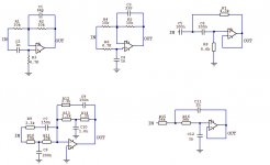
I have attached some common building blocks, delay/allpass (inverting and non-inverting), high pass filter, low pass filter and biquad/linkwitz transform.
I am looking for information regarding the calculation of input impedance, output impedance and the load presented to the opamp by each circuit.
I am looking for information regarding the calculation of input impedance, output impedance and the load presented to the opamp by each circuit.
Attachments
More than one of them have an input impedance which varies with frequency, so "calculating the input impedance" results in a function, a graph; not a single scalar number.
I recommend that you extract the plots you desire (Zin vs frequency), (Zout vs frequency), (Opamp output current vs frequency) from LTSPICE circuit simulations. Simulate using an opamp made by Linear Technology, since their SPICE models are more likely to be rigorously checked than others. (I would use the LT1498 in this case).
Once you've got those plots, you can print them out and put them in your Design Notebook forever. More importantly, you can use them to double check your work if you decide to calculate these same quantities by pencil-and-paper.
...calculation of input impedance, output impedance and the load presented to the opamp by each circuit.
Why? Or why do you care?
Part of the point of opamps is so you DON'T have to sweat impedances.
Rather: you make sure the lowest load is higher than the opamp's minimum load.
Most audio-good opamps will drive 2K.
Most of your circuits have 3.9K or 10K in-series-with everything else. 3.9K||10K makes 2.8K. It's OK because it is over 2K. You don't have to know how much over.
Yes, there are cases where it is NOT this simple. Sufficiently complex circuits can present negative impedances.
But these can be solved by inspection. One of them, I will call it "B", is clearly infinity for sub-audio and 4.7K||10K= 3.2K, no lower, for high frequencies. "C" is a little trickier: again infinity for LF and 8.6K in the passband, but the bootstrapped 4.3K is likely to cause a dip near the corner. I would sim that not for impedance but to check the response curve (it may be right, but I'd check).
Why? Or why do you care?
make sure the lowest load is higher than the opamp's minimum load.
in the context of a complete crossover network you may have a HPF block whose output drives an allpass block and a LPF block, thus the opamp of the HPF block has 3 loads, unless i am mistaken.
...has 3 loads....
So make all resistors several times higher.
Or use unity-gain buffers.
- Status
- This old topic is closed. If you want to reopen this topic, contact a moderator using the "Report Post" button.