I was looking at another low cost filter board, from the far east, to complement my active xo project. Budget active 3 way crossover - buy, eval, mod - diyAudio .
I actually wanted a bandpass more than just a lowpass. I wanted to attenuate the subsonic (<20Hz) as it causes wild movments in some types of subwoofers (BR, BP). In addition to setting the lowpass frequency and gain.
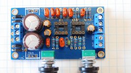
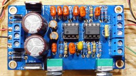
I saw a few different designs and settled on this one (see pic). It costs $8CDN but you have to assemble it yourself. It also has the same problem as all of them, no documentation or schematic. The irony is not lost on me. I bought parts to assembly, from probably the lowest cost assembly region in the world.
I bought this one because:
- it has terminal blocks for connections
- it uses a bipolar supply (see other xo), removes DC offset problems
- appears more complex than others (cap count, regulator, 2 dual opamps)
- potential to modify it, if needed (all through hole parts)
Note : there is a better board at Budget active subwoofer lowpass #2, buy, eval, mod that I prefer over the board in this thread.
I actually wanted a bandpass more than just a lowpass. I wanted to attenuate the subsonic (<20Hz) as it causes wild movments in some types of subwoofers (BR, BP). In addition to setting the lowpass frequency and gain.
I saw a few different designs and settled on this one (see pic). It costs $8CDN but you have to assemble it yourself. It also has the same problem as all of them, no documentation or schematic. The irony is not lost on me. I bought parts to assembly, from probably the lowest cost assembly region in the world.
I bought this one because:
- it has terminal blocks for connections
- it uses a bipolar supply (see other xo), removes DC offset problems
- appears more complex than others (cap count, regulator, 2 dual opamps)
- potential to modify it, if needed (all through hole parts)
Note : there is a better board at Budget active subwoofer lowpass #2, buy, eval, mod that I prefer over the board in this thread.
Attachments
Last edited:
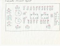
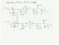
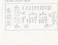
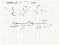
Layout and schematics
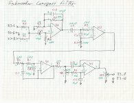
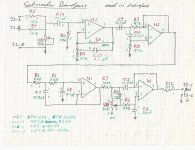
First, I need a layout and a schematic.
The power supplies are simple series regulators. They have both bulk electrolytics as well as a smaller decoupling cap for HF.
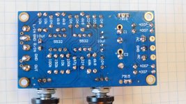
Mod#1 : the power supply section is designed for AC (tap 15Vrms), So it has a full bridge and the 15VDC regulators (LM7815 / LM7915). I plan on using the SMPS from my other project, which already supplies +/-15VDC. This lowpass board only use 25mA so I have plenty of spare capacity. The on board regulators will be eventually be replaced with LM7812 / LM7912 to run the opamps at +/-12VDC. Until I get these replacement regulators, I bridged the input-output of the regulators pads to run the board from +/-15VDC. That's why the regulators are missing on the first post pics. Runs fines.
First, I need a layout and a schematic.
The power supplies are simple series regulators. They have both bulk electrolytics as well as a smaller decoupling cap for HF.
Mod#1 : the power supply section is designed for AC (tap 15Vrms), So it has a full bridge and the 15VDC regulators (LM7815 / LM7915). I plan on using the SMPS from my other project, which already supplies +/-15VDC. This lowpass board only use 25mA so I have plenty of spare capacity. The on board regulators will be eventually be replaced with LM7812 / LM7912 to run the opamps at +/-12VDC. Until I get these replacement regulators, I bridged the input-output of the regulators pads to run the board from +/-15VDC. That's why the regulators are missing on the first post pics. Runs fines.
Attachments
Performance measurements, factory default
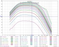
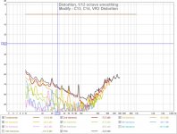
I ran a few freq sweeps using a REW and a soundcard loopback. The filter behave as a bandpass. Those extra caps are doing something.
Issue#1 : It seems the filter cutoff range (assuming -3db) is 100Hz-180Hz. I would like more low end range (ie. 60Hz). More problematic is the change in gain as you adjust the cutoff freq pot. You could use the other attenuation adjustment to bring it back down but I was expecting more constant gain vs cut off freq.
Issue #2 : Output attenuation pot. The way its implemented, the output impedance will vary as you change the attenuation. I would prefer a fixed 47R output impedance. This looks like a barnacle to fix Issue#1.
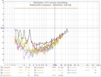
Issue #3 : The first input cap is a polarized electrolytic. The distortion is too high and I think this cap is causing a lot of it.
I ran a few freq sweeps using a REW and a soundcard loopback. The filter behave as a bandpass. Those extra caps are doing something.
Issue#1 : It seems the filter cutoff range (assuming -3db) is 100Hz-180Hz. I would like more low end range (ie. 60Hz). More problematic is the change in gain as you adjust the cutoff freq pot. You could use the other attenuation adjustment to bring it back down but I was expecting more constant gain vs cut off freq.
Issue #2 : Output attenuation pot. The way its implemented, the output impedance will vary as you change the attenuation. I would prefer a fixed 47R output impedance. This looks like a barnacle to fix Issue#1.
Issue #3 : The first input cap is a polarized electrolytic. The distortion is too high and I think this cap is causing a lot of it.
Attachments
@Scott, thanks for the link. ESP has a lot of interesting projects. Nothing jumps out in that specific ESP sub controller board.
I would like cutoff freq adj (60Hz-180Hz) independent of gain, and gain (-12db to +12db) independent of cutoff freq. I think that's reachable with this board. Most of the stuff is there, it just needs rearranging")
I would like cutoff freq adj (60Hz-180Hz) independent of gain, and gain (-12db to +12db) independent of cutoff freq. I think that's reachable with this board. Most of the stuff is there, it just needs rearranging
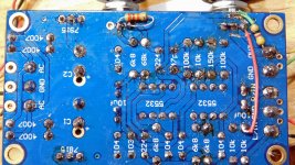
Modifications - input cap, first stage filter
I removed the electrolytic 10uF C14 (Issue#3) and replaced with a 0.1uf polypropylene. The reduction in distortion is dramatic. I can live with this, but there's room for improvement. Reducing the cap value also places another zero nearer to 20Hz to help the HP section.
I removed VR2 (Issue#2) and replaced with a 47R resistor. This makes the last stage a unity gain buffer with consistent low output impedance.
Capacitor C13 was increased from 47pf to 10nF (Issue#4) to limit the bandwidth of the entire system. Originally this filter rolloff was 33Khz. I don't have the preferred 6.8nf that I will eventually use (200Hz BW max).
Attachments
Last edited:
Modifications - independent freq adj
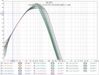
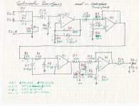
Mod #1 : lowered the gain U2-1, R9=47K for a gain of 3. When gain adj is implemented it will be at R9 with a pot.
Mod#2 : raised the HP fc to 23Hz. The HP filter at U2-7, R10=100K, R3=47K, butterworth 2nd order. It's to provide -15db attn @10Hz.
Mod#3 : the adj LP filter at U1-7, has VR1-1 tied to gnd that keeps the filter response damped but also creates a voltage divider. It's why the attn (-30db to 0db) changes with freq adj. I want freq adj independent of gain. The caps used C12 (0.22uf) and C6 (10nf) are too far apart in range and the damping coefficient is effected. You can see the 5db bump. Need a new compromise RC. Normally caps and resistors are 2x range for critical damping. Adj range is now 50-150Hz, probably reduce it to 60-120hz.
Note : there is a LP filter at U1-1 fc=160Hz BW2, that was left as is. Total attn after 160Hz is 24db/oct.
Attachments
Modification - independent freq adj and vol adjust
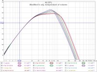
Frequency adjustment range (60-130Hz) still has a +3db bump. This is a compromise of trying to adjust a 2nd order filter using 1 pot. Ideally a stereo pot would allow adjustment of 2 resistive paths while maintaining Q without changing the gain. I could reduce this stage to a 1st order to make it flat, and overall it would be a 3rd order system roll off. I'll see how this goes, I prefer a 4th order system.
Volume adjustment was moved to the input stage. Range is from max gain (+9dB) to "off". I saw no need to limit the attenuation, I just needed at least 0+/-9db. One resistor change will increase the max (+9db) if I need it
Overall I have my subwoofer bandpass filter. Consisting of a fixed 3rd order subsonic HP (still need 1 cap value), and a 4th order adj LP with +/- volume adjustment. I'm very happy with that, considering it costs <$10 CDN with a few hours of measure and mod. I'll post an updated pic and schematic.
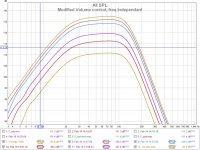
Attachments
Wrapping up
I got some budget regulators and some poly caps so this is the finished result. I ended up modifying a bit more than intended, but I got what I wanted.
Mod list:
1) replace regulators for +/-12VDC [Q2: 7915 -> 7912], [Q1:7815 ->7812]
2) replace input electrolytic (C14) with polyprop 0.1uf
3) cut 2 tracks to VR2, add jumper to R4-2 to attenuate/boost input
4) replace R9 [10K -> 47K]
5) replace C13 [47pf -> 100pF]
6) replace R3 [6K8 -> 47K]
7) replace R10 [47K -> 100K]
8) replace R7 [10K -> 100K]
9) add R13 [22k] across VR1-3 to VR1-2
10) replace R6 [100K -> 6K8]
11) add R12 [47R] to output J3-1
Attachments
integrating to a 3way active
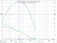
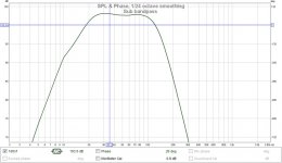
I have a 3way active XO that this will eventually integrate with. So I wanted to flatten the passband and adj the HP. The FR and updated schematic attached. I suspect the freq adj pot will be removed to improve the LP and make it a LR4@100Hz eventually.
Mods :
gain adj : R9=22K
HP rolloff + damping : R3=22K, C9=C10=0.15uF
Attachments
I used this ebay subwoofer board in quite a number of active crossovers. I always follower andrea ciuffolis mods.
The Monitor 4
The Monitor 4
Nice work, Don. Thanks for sharing - this looks very useful for a FAST.
Now, if only the chap in China would take this, and make it so we don’t have to futz with it at all!
A little more engineering effort should have been put into this design
before it was released. The parts count is basically the same after modifying it, so the BOM cost would've remained the same. Still, for less than $10 cdn, it was fun to tinker with and I have a sub bandpass filter.I used this ebay subwoofer board in quite a number of active crossovers. I always follower andrea ciuffolis mods.
The Monitor 4
Thanks for the link.
That filter (in link) seems to have the same issues as the one I bought. It might even be an earlier revision. I can't imagine anyone thinking that having the gain vary with the freq adj was a good thing. There's probably a "fixed" version just waiting for the old stock to clear
I really enjoy reading your dissection of the crossover PCB design and the performance measurement. This forum needs more post like this.I got some budget regulators and some poly caps so this is the finished result. I ended up modifying a bit more than intended, but I got what I wanted.
Mod list:
1) replace regulators for +/-12VDC [Q2: 7915 -> 7912], [Q1:7815 ->7812]
2) replace input electrolytic (C14) with polyprop 0.1uf
3) cut 2 tracks to VR2, add jumper to R4-2 to attenuate/boost input
4) replace R9 [10K -> 47K]
5) replace C13 [47pf -> 100pF]
6) replace R3 [6K8 -> 47K]
7) replace R10 [47K -> 100K]
8) replace R7 [10K -> 100K]
9) add R13 [22k] across VR1-3 to VR1-2
10) replace R6 [100K -> 6K8]
11) add R12 [47R] to output J3-1
I have a question about the regulators. The 78xx/79xx pair are very convenient to use, but difficult to match. I was building a +/-15 volts supply. I got 10 each of the 7815 and 7915, but I could not find one single pair that were close in voltage numerical values. The closest pair I got were +15.23V and -15.08V. Any randomly selected pair could be 0.2 to 0.6 volt apart. Does the asymmetrical voltage matter? What do you do about it?
I do not use the board because I want a low pass section for the main speakers too. I end up using this:
Preamplifier Crossover 2-Way Electronic Frequency Divider board Free adjustable 831230323184 | eBay
The subwoofer crossover will be 120 Hz.
I really enjoy reading your dissection of the crossover PCB design and the performance measurement. This forum needs more post like this.
I'm glad you enjoyed it, thanks.
I have a question about the regulators. The 78xx/79xx pair are very convenient to use, but difficult to match. I was building a +/-15 volts supply. I got 10 each of the 7815 and 7915, but I could not find one single pair that were close in voltage numerical values. The closest pair I got were +15.23V and -15.08V. Any randomly selected pair could be 0.2 to 0.6 volt apart. Does the asymmetrical voltage matter? What do you do about it?
I don't worry about it. These regulators are only 2% accurate anyways. This board's regulators were measured at (+12.21VDC and -11.93VDC) so the op-amp is powered off 24.14VDC. The signal ground is set by the power supply and all signals are referenced to it (note: no gnd pin on the op amp). It would not matter if the supply was "a little" asymmetric.
I have another 3-way crossover that uses shunt regulators instead of these 78/79xxx series regulators. It measures +12.14VDC and -12.13VDC and uses the same op-amps. The op-amp performance is the same in both cases from what I've measured.
I do not use the board because I want a low pass section for the main speakers too. I end up using this:
Preamplifier Crossover 2-Way Electronic Frequency Divider board Free adjustable 831230323184 | eBay
The subwoofer crossover will be 120 Hz.
I intend on using a sealed chamber for the woofer. So it will have a 2nd order (-12db/octave) acoustic rolloff at approx. 100Hz. Otherwise I'd have the same issue as you described, and would need to bandpass the woofer as well.
Have you used the board you mentioned ? If so do you like it?
I am waiting for the delivery of the board, a 12dB 2-way using state variable filters. It will be a few more week before I have the active crossover put into service. I will post the result and some pictures when I am done.I'm glad you enjoyed it, thanks.
I intend on using a sealed chamber for the woofer. So it will have a 2nd order (-12db/octave) acoustic rolloff at approx. 100Hz. Otherwise I'd have the same issue as you described, and would need to bandpass the woofer as well.
Have you used the board you mentioned ? If so do you like it?
My main speakers are two closed box bookshelf 2-way with a -3dB point at about 80Hz. I received a lot of help on this forum before I finalized the passive crossover for it.
The crossover for a modest DIY bookshelf speaker project
The subwoofer is a pair of modified Wharfedale using a pair of 7" woofers. I have 3 of these. The 2 that I used for sub work really well. But the one that I mod for center speaker really has too much bass for that application.
For many years, I used the surround sound processor (Rotel RSP-1570) to manage the subwoofer. Last year, when I downsized my home, I also downsized my main audio system to a 2.1 channel (more accurately, 2.2) setup using the same front speakers. I got an Emotiva USP-1 preamp with bass management for the sub, but do not really like the overall sound. I switched back to my Harman Kardon AP2500 classic preamp and start to build my sub crossover. Wish me luck.
Last edited:
The inputs are capacitively coupled and summed at the op amp. The circuit is powered by a floating SMPS supply (+/-15vdc) so the local power gnd is also the local signal gnd. This allows the input gnd and local signal gnd to be connected without creating a DC bias.
Last edited:
- Status
- This old topic is closed. If you want to reopen this topic, contact a moderator using the "Report Post" button.
- Home
- Source & Line
- Analog Line Level
- Budget active subwoofer lowpass, buy, eval, mod