I was looking for a simple buffer circuit to replace the opamp in a unity gain stage of my active filter.
I found an old circuit by E. Borbely which has an advantage (to my opinion) because it uses only n-channel fets. Unfortunately the Jfets that are used were not easy to find and similar types were rather expensive.
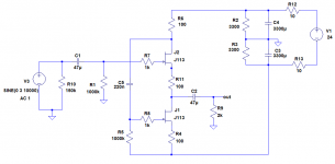
After some searching I decided to use the J113 fets and adapt accordingly the values of the components.
The circuit was analysed with LTSpice and the final version that I built is shown in the attached file.
The measurement results were very good. After matching the two jfets, I measured the output offset at about 1mV. The maximum signal output is +/- 8 V peak and the frequency response more that 100 kHz. The distortion at 2.2 Vrms / 2 kOhm is very low, similar to the capability of my measurement system which is at about 0.015%. According to LTspice the THD is 0.003%.
Any remarks or comments are welcome.
I found an old circuit by E. Borbely which has an advantage (to my opinion) because it uses only n-channel fets. Unfortunately the Jfets that are used were not easy to find and similar types were rather expensive.
After some searching I decided to use the J113 fets and adapt accordingly the values of the components.
The circuit was analysed with LTSpice and the final version that I built is shown in the attached file.
The measurement results were very good. After matching the two jfets, I measured the output offset at about 1mV. The maximum signal output is +/- 8 V peak and the frequency response more that 100 kHz. The distortion at 2.2 Vrms / 2 kOhm is very low, similar to the capability of my measurement system which is at about 0.015%. According to LTspice the THD is 0.003%.
Any remarks or comments are welcome.
Attachments
They don't have much current capabilities so don't know if this will be a good buffer design. As such buffers are current amplifiers . Also these Jfets have a significant gate capacitance. No noise specs available. General concensus is to use Bf862 these days with good specs in the designs Similar to yours ( it is a Feucht buffer) or cascode them if you plan to input more than 2 V. I recently posted some designs and even made a board for the same.
B1 design by Nelson pass also uses same principle but drives the Jfets near IDss ( saturation) which gives them immunity against power supply issues.
Calvin's cascoded buffer is also a great option with low part numbers and good noise figures and has very good reviews by users. I have a schematic posted under BJD buffer thread.
My board basically has a Jung Diden power supply to provide immunity for PsSR and noise and can drive them below Idss with suitably matching both source resistors.
Regardless all these designs need closely matched Jfets and if possible thermal coupling ( except cascoded ones who only need matched devices)
Last edited:
Hi
Every single-device buffer will have miserable THD compared to even a crappy opamp wired as a buffer.
Yu can build discrete circuits to use as buffers, but as you refine the performance the complexity often increases to where you have a discreet opamp. This can perform better than an IC and has the advantage that you have many degrees of freedom for improvement, i.e. you can raise the supply, change compensation, change devices, etc.
150ppm is pretty bad for a buffer; 30ppm is better but still kind of 1960s performance for good discreet preamp circuitry. You should be getting six-zeroes at the voltage and load you specified. This is easy with a full-complementary bipolar circuit with EF-VAS and EF output - easier with an EF2 and then you can drive 100R at tens of parts-per-billion THD20.
Hi,
I agree to the first part of Your reply.
The super-simple circuits are rather limited regarding THD, and current drive capability I might add.
But if one doesn't need the current the Q remains if the lower THD of more complex circuits improves the sonic performance.
Cascoding the above buffer with two more JFETs would already sink the THD considerably but hardly changes sound at all.
Adding a pair of bipolar PNPs to the above or the cascoded buffer (hybrid compound or hybrid Siklai pair, Calvin buffer) will reduce THD even more with the advantage of increased current drive capability.
In my ears this configuration adds 'authority' to the sound.
If it weren't for that I wouldn't implement it, just to see one or two more zeroes on a display.
Which leads to the second part of the reply.
Why should stellar THD figures be any good sonic wise? ..... besides it'll be almost impossible to verify six zeroes or parts per billion.
jauu
Calvin
Thank you all for your comments.
My intension is to use this circuit as a buffer in an active crossover. So there is no need to drive heavy loads with high currents. A voltage drive of 2Vrms at 2 kohms, I think is more than enough for my purpose.
Of course an opamp will have much more better distortion figures, but I would agree with Calvin's comment. Is there a sonic merit if the distortion has 3 zeros instead of 1 or 2?
Another JFet that I could use is BF862, the only problem is that comes only as an SMD component.
Can you recommend any other easily available through hole JFET?
regards
George
IMHO you are unnecessarily restricting your choice by ruling out SMD.
Why not just use a SOT23 to TO92 adaptor ?
Adapter SMD TO23 -> RM2,54, 0,30 €
For 2k load you can use BF862 (obsolete) or 2SK3557.
For 10k load 2SK209 will do, and consumes much less current.
Cheers,
Patrick
Why not just use a SOT23 to TO92 adaptor ?
Adapter SMD TO23 -> RM2,54, 0,30 €
For 2k load you can use BF862 (obsolete) or 2SK3557.
For 10k load 2SK209 will do, and consumes much less current.
Cheers,
Patrick
Hi
For the circuit in post-1 the supplies have to be rock solid and very clean since the circuit is push-pull with internal signalss referenced to the rails.
Electronic distortion is unnatural to our hearing - we did not evolve with it and therefore expend a great deal of energy filtering it out when listening to electronically amplified sound. The lower that distortion can be made, the easier time our brains have and we can enjoy the music better. So, for me, low-THD is paramount and it always improves the sound of the music.
You may prefer "excitement" over "accuracy" and it is ultimately each person's subjective impression that drive their search for "good sound" in one direction or another. For some, the subjective and objective converge; for others they diverge.
I've built active crossovers as well. I decided to go for low-Rs and high-Cs to keep noise as low as it can be even though there is very little gain after the crossover. This meant having buffers that can drive 100R to give a nice margin and that meant 12-device discreet opamps.
Because of the limitations of all electronic circuits, it is a good idea to have a low-pass filter at the input and output that will band-limit to 100kHz. The decreasing gain for feedback can actually allow very-high-frequencies to rise up in amplitude. In spice, you should extend the frequency response test t at least 1Ghz to see if this happening in your circuit.
The PSRR of the White Follower can of course be improved upon significantly with the Taylor current source.
Taylor Source Follower
Patrick
Taylor Source Follower
Patrick
I think you are right concerning the SMD. I will consider also the BF862 or 2SK3557.
Any other suggestion?
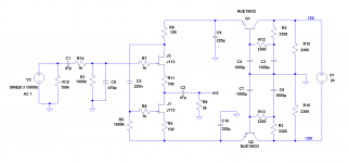
The quality of power supply voltage is always a very important issue for me.
The modified circuit with the power supply I will use is shown in the attached file. The 24 Vdc will be produced by an external switching power supply from XP Power.
Any comments?
Any other suggestion?
The quality of power supply voltage is always a very important issue for me.
The modified circuit with the power supply I will use is shown in the attached file. The 24 Vdc will be produced by an external switching power supply from XP Power.
Any comments?
Attachments
Depends on how much perfection and PSRR you want. Well, most answer the best they can get. Either salas shunt reg or Jan diddens design is the only one that I know with salas tad better , not to a great margin. There are lot of other options with std voltage regulators available ( mostly SMD ) which needs careful layout to work to full potential. I am not an expert and can't say about your specific power supply attached.
The 24 Vdc will be produced by an external switching power supply from XP Power.
Any comments?
If the switcher gives only the single 24V output you will have to provide a virtual ground to make it +-12V.
I was looking for a simple buffer circuit to replace the opamp in a unity gain stage of my active filter.
I found an old circuit by E. Borbely which has an advantage (to my opinion) because it uses only n-channel fets. Unfortunately the Jfets that are used were not easy to find and similar types were rather expensive.
After some searching I decided to use the J113 fets and adapt accordingly the values of the components.
I have lots of J113's and have compiled quite a bit of data on their use as
buffers.
Typical sort of number at 2V output is about .015%, which is 2nd harmonic.
If you want better you have to tweak the resistor values against the
specific pinch-off voltages of the parts, and the lowest you can get is
around .004% or so. This requires a good distortion analyzer, and is very
specific to a load value.
Either way, the sound is quite good.
Nelson, I am very happy with your comment about the sound quality.
Unfortunately my analyzer cannot measure below 0.015%, but LTspice gives a THD of 0.003% which is very close to what you have measured in a real circuit.
I also noticed on the simulation that when there is a specific load resistance at the output, there is a minimum in the distortion by changing the value of resistance R6.
Do you also have such experience in a real circuit ?
Why bother with J113 or else when you can use 2x 2SK209GR to make up a 2SK170BL-equivalent ?
If you are worried about heat, just glue a small heatsink on top.
ICK SMD A5: Kühlkörper SMD 6,3 x4,8x 5,0mm, Boden 1mm bei reichelt elektronik
B1-Turbo on a Chip
2SK209-GR(TE85L,F) Toshiba | Mouser Europe
Patrick
If you are worried about heat, just glue a small heatsink on top.
ICK SMD A5: Kühlkörper SMD 6,3 x4,8x 5,0mm, Boden 1mm bei reichelt elektronik
B1-Turbo on a Chip
2SK209-GR(TE85L,F) Toshiba | Mouser Europe
Patrick
Hi,
Your buffer requires indeed a decent supply, but the SMPS plus post filter should suffice.
I built my ESL xover just the same way using 2SK373 ... not the prime choice for this application, but I have them by the thousands lying around.
It was the most authentic and real sounding xover, beating a OPAmp equipped but otherwise identical xover hands down and most DSP based filters also.
I'd suggest to test and listen the buffer before building the complete xover.
Two tips You might consider:
- bass performance improves with more capacitance directly at the JFETs. Still though this kind of buffer will probabely never be the bass master.
- Adding PNPs in Sziklai style not only improves current drive capability, but also adds slam and authority to the sound. At least the ouput buffers/cable drivers certainly profit from better drive.
jauu
Calvin
- Status
- This old topic is closed. If you want to reopen this topic, contact a moderator using the "Report Post" button.
- Home
- Source & Line
- Analog Line Level
- JFET buffer with J113