What do you REALLY expect here?
Do you, for some bizarre reason, think the the NE5532 and 5534 are the "Holy Grail" of op-amps when it comes to sound quality?
If so, I can tell you without a shadow of doubt that they are NOT having trying many op-amps in many different applications over the years.
Why don't you throw the '5534 and its dual counterpart '5532 in the trash where they belong and move on to other more modern and better sounding op-amps?
You have a LOT to learn about audio op-amp circuits, so I wish you nothing but the best of luck with your venture!


And that is about the most unhelpful and arrogant reply to someone who struggling to get a basic circuit to work at all. Op-amp rolling! Give me a break!
The most likely problem here is something very miswired, wrong value component and / or oscillations.
How have you built this circuit? Can you show a clear photo of the components?
Unless something is really askew, an opamp circuit with fixed gain (set by resistor values) will be flat across the audio band. So something is DRASTICALLY wrong. This is difficult for a beginner with no test equipment and limited knowledge.
The 1pF cap bothers me! That is the capcitance of two wires close to each other!
Check all your components and values, post the clearest possible photos.
there is nothing wrong with the ne5534/32. They can have good bass its just logical the culprit is the circuit design.
I don't have my camera now and the amp is packed away again! But then what will you see as the circuit diagram is very accurate!
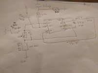
With the exception of another resistor at input the circuit for ne5534 is highly accurate.
Rayma kindly suggested changing the 30k to 100k and it worked except for the massive DC offset. Even I know 200mv is very bad!
And that the only real progress!! Ne5534 is fine, the is no distortion etc. The sound is excellent just needs more bass!!!!! Bit flat and bright thats all.
I'm willing to bet money its one or two resistors but only an expert can say which ones! Help!! Please!
I don't have my camera now and the amp is packed away again! But then what will you see as the circuit diagram is very accurate!
With the exception of another resistor at input the circuit for ne5534 is highly accurate.
Rayma kindly suggested changing the 30k to 100k and it worked except for the massive DC offset. Even I know 200mv is very bad!
And that the only real progress!! Ne5534 is fine, the is no distortion etc. The sound is excellent just needs more bass!!!!! Bit flat and bright thats all.
I'm willing to bet money its one or two resistors but only an expert can say which ones! Help!! Please!
Attachments
there is nothing wrong with the ne5534/32. They can have good bass its just logical the culprit is the circuit design.
I don't have my camera now and the amp is packed away again! But then what will you see as the circuit diagram is very accurate!
With the exception of another resistor at input the circuit for ne5534 is highly accurate.
Rayma kindly suggested changing the 30k to 100k and it worked except for the massive DC offset. Even I know 200mv is very bad!
And that the only real progress!! Ne5534 is fine, the is no distortion etc. The sound is excellent just needs more bass!!!!! Bit flat and bright thats all.
I'm willing to bet money its one or two resistors but only an expert can say which ones! Help!! Please!
It sounds like there is something wrong with the circuit you have put together.
But on the offset - first I'd say that 200mV isn't that big a deal wrt +15V supplies (max output, say circa 13V depending on load ) so just losing a bit of headroom. With a 5534 you'll need to ac couple the output in any case and the amp you're feeding almost certainly has ac coupled input in any case.
But to get reduce it to by getting rid of the gain at DC then you put a big ol' cap between the resistor from the -ve input that currently goes to 0V and 0V.
ie detatch it from ground and put a cap in the gap. If using polarised electrolytic with 5534 then put -ve cap pin to 0V.
Gain at DC is then unity.
Bass in subjective lend depends firsthand on power rails capacitance. 10 000 uF each rail .... try, You will lovw it
You don't need anything like that capacitance.
It's not a power amp !
What you need depends on the power supply and physical arrangement / cable lengths etc.
In general any reasonable value of bulk decoupling where the power comes onto the board - 100uF is fine. One per rail to 0V.
Then say 100nF Ceramic or Polyester between +15V and -15V near the 5534.
You may want to put small, say 10R, resistors or ferrite beads in series with the +/-15V rails to the 100nF cap.
However I do see from the sketch that only one 22uF cap is shown between +15V and -15V and the +15V isn't shown as connected to anything else - I assume it is actually connected on the hardware.
Please don't tell me this isn't enough - I have a bunch of circuits about 10m away from where I am sitting that shows it does - apart from thousands of audio circuits and channels in operation.
Anyway, unless the OP has stability / oscillation problems this isn't the issue.
Last edited:
To keep the DC offset low, you need to keep the resistances the the inputs see balanced like you have now (36k + 4k7 positive in) and (43k || 220k negative in).
Another wiggle you could try is to up the 36k to 39k, reduce the 4k7 to 1k8 or 1k5; and up the 220pF cap some - I'd try 470pF and go up to 1nF...
Of course, upping the 2u2 input cap would add more bass impact than any of above.
Another wiggle you could try is to up the 36k to 39k, reduce the 4k7 to 1k8 or 1k5; and up the 220pF cap some - I'd try 470pF and go up to 1nF...
Of course, upping the 2u2 input cap would add more bass impact than any of above.
Hi dj_holmes,
I wonder if that op amp isn't oscillating. The 1 pF capacitor across the 220K in the feedback network isn't enough. Your gain is also really high. If anything, you should be hearing bass without much in the way of highs.
Try increasing the 1 pF capacitor to 22pF and go higher. If you have an oscilloscope, you could easily see what the circuit was doing. The NE5534 is an excellent op amp for audio.
Your DC offset isn't surprising since your gain is so high. You might want to break down the stage into two op amps with each at a reasonable level of gain. You can control things much better and your DC offset should really drop to the < 10 mV level
-Chris
Wow lots of input!
1, Ok I tried 4.7uf bipolar on the 2.2uf input had little effect
2, the 1pf changed to anything higher than a 5pf sounds muffled. i.e no treble and sounds hollow the higher the capacitance
3, I have to trace the circuit to find where the + supply for the opamp is coming from but currently can only find 1 22uf power cap.
4, the DC offset was only high when the 30k input resister was changed to 100k otherwise DC offset is normal
5, the opamp is dual power so I have been told 100nf from each power supply to ground is recommended.
6, tried changing the 220pf for something slightly higher and has little effect with high frequency.
I know the Ne5534 is a good opamp so changing that is really last resort.
Love reading the suggestions!!!
Hi rmaudio,
That is stunningly clear, I was only addressing concerns that dj_holmes had brought up earlier. Your input wasn't very helpful. Try to bring some information to the conversation in future, rather than poke away at someone. After all, what I said was true.
Hi dj_holmes,
Replacing the 5534 will only bring you another op amp with soldered leads. I hope you aren't using a socket.
1.) That was expected
2.) Lower the resistance and use a higher value feedback capacitor. Limit the gain to something more reasonable as I think you are trying to get more from one stage than you should. Stray capacitance from the board could be causing some of your problems too.
3.) Who made the board, or are you using a prototyping plug in strip?
4.) Okay, that is expected as well.
5.) Yes, but the world won't end unless there are no filters on the negative rail.
6.) Yes, that is determined by the impedance of the device sending the signal as well as your own component values.
Why not try cutting your feedback resistors by 10, so a 22K feedback resistor with the leg to signal common at 4K3? That will also allow you to use normal values of capacitance for your feedback compensation cap (now 1 pF).
-Chris
Hi Chris,
the amp is already built! I didn't build it. My buddy acquired it and it was unbranded (probably brand rubbed off) case is a bit tatty.
Sorry which resistor should I cut back? Can you possibly refer to original value?
The amp is stored away but I'm hoping to fish it out tomorrow or day after and try all possible solutions offered here
Hi dj_holmes,
Was this commercially made, or a home brew amplifier? There is a different approach for each situation. Commercial equipment can be assumed to have worked at some point in time. Home-made things do not have any guarantees that at one time they functioned properly.
Before doing anything, can you take a picture of the area and confirm whether it was made in a factory or a garage?
-Chris
The parts are high quality nothing is failed, everything is working perfectly fine just needs more bass less treble not even by much!
This is not home made looks commercial.. I can only take pics once I start work on it this is why I need the info. I need to drop it to my mates house too as not only does he need it but its actually for him!
This is not home made looks commercial.. I can only take pics once I start work on it this is why I need the info. I need to drop it to my mates house too as not only does he need it but its actually for him!
Hi dj_holmes,
I'm at a loss as to why it is light in the bass department. It shouldn't be. Do you have access to an oscilloscope? I want to make sure it isn't oscillating above your range of hearing. What would be nice right about now is an oscillator and an AC meter to confirm it is low in bass output and at what frequency the drop-off begins (-3 dB point).
-Chris
Hi dj_holmes,
I'm at a loss as to why it is light in the bass department. It shouldn't be. Do you have access to an oscilloscope? I want to make sure it isn't oscillating above your range of hearing. What would be nice right about now is an oscillator and an AC meter to confirm it is low in bass output and at what frequency the drop-off begins (-3 dB point).
-Chris
I do actually have a kit version I built but dont know how to use it. To be honest I do understand what you are saying but I just dont have that time to spend on it. Changing a few caps or resistors with advice is great but getting scopes out etc I'm lost and it seems to much work to please a friend. I'm going to hell for that last comment aint I?
Hi dj_holmes,
The instruments will save you a great deal of time.
If it were me, I would change the feedback components. But, I also would have looked at the thing with instruments already. You can't change things without knowing where you where and where you are afterwards. It's a commercial product (not well designed), and so you have to assume it worked at some point. If it was cheap, it may not have worked well, but it worked in some fashion. You may be fighting against the design of the thing.
Anyway, at least connect some scope leads in there and see if it's oscillating. It would be easy to see if the bass frequencies were really cut off or not. A bunch of answers in a short time if you would only use your equipment. Plus, you are gaining experience, there is a benefit here for you. Take the opportunity and learn.
-Chris
Hi rmaudio,
That is stunningly clear, I was only addressing concerns that dj_holmes had brought up earlier. Your input wasn't very helpful. Try to bring some information to the conversation in future, rather than poke away at someone. After all, what I said was true.
-Chris
Well what I said was true too. Big Deal.
The point is that the OP risks being distracted from a solution to his actual or perceived problem. And the comment re Offset was not especially targeted at your input - there was a suggestion of balancing the impedances seen by the op amp inputs to reduce offset. This is correct but there's a noise penalty for no real audio benefit.
Don't presume to tell me what to do "in future". Understand ?
FWIW I agree that the high resistor values and 1pF hf feedback cap are an issue.
If 1pF to 5pF is giving a problem then there's likely to be layout / stray capacitance problems. Plus resistor noise for no benefit.
Plus , yes, needs to check for instability / oscillation.
- Status
- This old topic is closed. If you want to reopen this topic, contact a moderator using the "Report Post" button.
- Home
- Source & Line
- Analog Line Level
- NE5534 circuit. I need more bass. Help!!