I have just been reading a great thread here from 2013 which has been very helpful, outlining the wiring of a standard stereo volume pot for attenuation of a balanced signal.
http://www.diyaudio.com/forums/analog-line-level/161593-wiring-balanced-volume-pots-2.html
I have keyed the calculations outlined into a spreadsheet which is now calculating the attenuation at various different POT positions with different series resistors and variable resistor values and also telling me the input impedance seen by the source looking into the passive Pot and the Amp.
My main question is, what is the output impedance from this circuit and how can this be calculated? Surely there is a limit to the size of variable resistor (POT) that can be used without causing an issue upstream looking into the power amp?
I have searched through several threads on similar subjects for balanced passive Pots wired in this manner and have seen a suggestion that the output impedance is simply the value of the variable resistor. If this is the case, is this in parallel with the output impedance of the source? Should the variable resistor value be kept reasonably low bearing in mind the input impedance seen by the source of course?
In my case I have the following two bits of kit that I am looking to build a passive balanced monitor control for.
RME Fireface 400 = 75ohms output impedance
Hypex Ncore = 47Kohm from + to ground and 47Kohm from - to ground
many thanks in advance.
Show us the circuit. The thread page you linked to does not specify a circuit.
In general, the output impedance of a pot (assuming low source impedance) is the parallel combination of the two parts of the track. If you have two pots in a balanced configuration then add the two values (as they are likely to be the same then just double them).
In general, the output impedance of a pot (assuming low source impedance) is the parallel combination of the two parts of the track. If you have two pots in a balanced configuration then add the two values (as they are likely to be the same then just double them).
Hello and thank you for your reply.
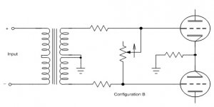
Yes sorry that was not very clear of me. The link posted in that thread is below, I have attached the schematic from the link however whch shows the wiring. two matched resistors on each + and - line and then the pot wired as a variable resistor between the - and + lines of the balanced connection. no connections to ground.
It is only the volume control part of the diagram (excluding the valves and transformer) that I was looking at making as were the people who were discussing this in that thread from 2013 also.
Chapter 4
(Figure 17)
Yes sorry
Attachments
You now show us two different circuits.
For the first circuit the output impedance will be 'pot resistance setting' in parallel with 'sum of series resistors' - assuming small source impedance. The output impedance peaks at maximum volume. Minimum impedance will be zero at zero volume.
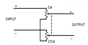
For the second circuit the output impedance peaks at pot mid position (mid position in resistance, not necessarily pot travel). It will be equal to 'pot resistance'/2. Minimum impedance will be at max or min volume.
For the first circuit the output impedance will be 'pot resistance setting' in parallel with 'sum of series resistors' - assuming small source impedance. The output impedance peaks at maximum volume. Minimum impedance will be zero at zero volume.
For the second circuit the output impedance peaks at pot mid position (mid position in resistance, not necessarily pot travel). It will be equal to 'pot resistance'/2. Minimum impedance will be at max or min volume.
You now show us two different circuits.
Heck, sorry! I uploaded the wrong attachment, I was supposed to upload a simplified version of the first attachment showing just the variable resistor and two fixed series resistors.
Thank you for your kind help.
If designing this passive monitor control to have the least negative influence over bandwidth and signal transfer from source to power amp, do I need to be mindful of the output impedance from the POT wired as shown in the first attachment?
Or, is it really just about checking the impedance that the source sees looking through the passive monitor control and into the power amp? As long as there is a good ratio here, say 1:10 or more, does this output impedance figure in isolation matter at all?
Many thanks again.
The output impedance depends on the adjustment of the potentiometer.
In general, it is not a good idea to have a passive preamp.
Certainly there seem to be some factors and limitations to be aware of, but I have built a couple of passive, single ended attenuators that have worked well in the past, with short cable runs of course.
The simplicity, once it is built certainly seems attractive. Using a stepped attenuator for the variable resistor seems like a good idea to give better channel tracking, as does matching as closely as possible the series resistors.
The output impedance matters because it is that which drives any cable and the input impedance of the amplifier. Two issues:
- cable capacitance (plus any RF filter at th4 amp input) - this can degrade HF response
- amp input impedance - in some cases this can be nonlinear and introduce distortion
You have 75R source, and 94k load. The impedance to aim for in the middle is thus around 2-3k (= sqrt(source x load) ). You have some leeway on this so perhaps a 10k pot would do, with 2-3k series resistors. Of course with a shunt pot like that you will have attenuation even at max volume.
- Status
- This old topic is closed. If you want to reopen this topic, contact a moderator using the "Report Post" button.
- Home
- Source & Line
- Analog Line Level
- Passive Balanced Volume Control Output Impedance?