Sage advice.beware trying to sim, most macro models don't correctly show PS pins affecting compensation when in real 5-pin op amps the Cdom is connected to one of the PS rails
...lots of output voltage capability that can be used to drive unity gain amplifiers....
To state the obvious: what you want is a classic transistor Power Amp, minus the output stage. Such things are easily built and easy to find plans for; re-rig the output side minus the power stage.
Specifically the MoFo: its input is such an easy drive that you probably only need input pair and the VAS stage, no emitter followers or their bias.
Hi Charlie and the thread...
Now that you have 15 suggestions to do this, why not a 16th?
Actually, this might be interesting for a topology suggestion. I like the linear pot providing a log slope trick. With a bit of design work (even virtual with LTSpice) it might be adjusted for 0-20dB, rather than -20dB-0dB. That, and a higher rail opamp, and you're good to go... Too bad TI isn't selling boards for this, pretty simple layout though...
http://www.ti.com/lit/ug/tidu034/tidu034.pdf
With a bit of design work
You can achieve pretty logarithmic regulation a step better than best log potz could achieve with only linear potz.

To state the obvious: what you want is a classic transistor Power Amp, minus the output stage.
LM4702, LME49830, LME49810, LME49811 -- all gone to heaven, but still available if you look.
If "high voltage" is only +/-24v, the opa604 has no problem with it. But it's not able of a rail to rail output, so you'll be limited at about 42vp-p
This OPA604 (low distortion, low noise, high slew rate, unity gain stable) with + - 24v rails seems to me to be the simplest way of getting high gain high output. Which is what the title is? And it comes in an identical dual OPA2604, But I like the single as you can direct couple it and have DC Offset trim on it.
"op-amp based, high-gain, high rail voltage, preamp"
Don't know why everyone is intent on complicating things.
Cheers George
Last edited:
LME49860 is +&- 22V Rail to rail.
See here about measured performance of this op amp.
Bridged Buffered Opamp Amp - a journey
See here about measured performance of this op amp.
Bridged Buffered Opamp Amp - a journey
Low offset. It does not need a trimpot in this audio application: Bridged Buffered Opamp Amp - a journey
Low offset. It does not need a trimpot in this audio application: Bridged Buffered Opamp Amp - a journey
Bet it's got some, never seen one yet that's only a couple of mV. And it's going to compound anything that the input sees from the source as well, with all that gain.
Cheers George
Of course it got some.
However there is no need for a trimpot in most audio applications.
LME49860 input offset voltage is 100 micro volt.
Yes but whatever dc comes in, as I said is going to compound as well because of the gain you have!
Unless you cap couple the sources output or the input of the LME, like I said I hate coupling caps.
Cheers George
The LME49860 typical Vos is 100µV, but the input bias current is 10nA, and both have to be considered in the specific circuit, as should the circuit's noise gain. Don't get me wrong, this amplifier is beautiful, it has extremely low distortion, but offset has to be considered in terms of what you're doing with the amplifier. The passives around the amp that might tickle the input bias current, and the circuit's noise gain will scale the total offset up further.
I too dislike coupling caps, and have found that DC servos can be made to work well and provide a 'one stop' offset control solution, at the expense of a lot of extra parts and a good bit of design. They can be made to work well, but there are also a lot of ways to make pretty awful servos. I'm using the lower voltage version of the LME49860 (the LM4562) in a project and I've found that an Analog ADA4522-2 can make a really ideal servo with a total 'end of the day' offset of around 6-10µV, with little added noise or distortion. You have to do some tricks to make sure that the amp won't contribute noise or distortion to the output, or mess up the passband response, but this can all be done. The typical decades old servo designs seen on the 'net using a TL072 or other sloppy BiFET amp as a servo amp won't cut it. And, a trimpot gets adjusted once, and remains there forever, despite temperature, time, and input DC offset - a servo is a far better plan.
I too dislike coupling caps, and have found that DC servos can be made to work well and provide a 'one stop' offset control solution, at the expense of a lot of extra parts and a good bit of design. They can be made to work well, but there are also a lot of ways to make pretty awful servos. I'm using the lower voltage version of the LME49860 (the LM4562) in a project and I've found that an Analog ADA4522-2 can make a really ideal servo with a total 'end of the day' offset of around 6-10µV, with little added noise or distortion. You have to do some tricks to make sure that the amp won't contribute noise or distortion to the output, or mess up the passband response, but this can all be done. The typical decades old servo designs seen on the 'net using a TL072 or other sloppy BiFET amp as a servo amp won't cut it. And, a trimpot gets adjusted once, and remains there forever, despite temperature, time, and input DC offset - a servo is a far better plan.
Could you post the DC servo schematic that you use?............... have found that DC servos can be made to work well and provide a 'one stop' offset control solution, at the expense of a lot of extra parts and a good bit of design. They can be made to work well, but there are also a lot of ways to make pretty awful servos. I'm using the lower voltage version of the LME49860 (the LM4562) in a project and I've found that an Analog ADA4522-2 can make a really ideal servo with a total 'end of the day' offset of around 6-10µV, with little added noise or distortion. You have to do some tricks to make sure that the amp won't contribute noise or distortion to the output, or mess up the passband response, but this can all be done. The typical decades old servo designs seen on the 'net using a TL072 or other sloppy BiFET amp as a servo amp won't cut it. And, a trimpot gets adjusted once, and remains there forever, despite temperature, time, and input DC offset - a servo is a far better plan.
Are there any guidance/rules we need to follow to get the same good performance you achieve?
How stable is it?It’s all detailed in my thread post 1.
JRC5534D.
It seems to me that the compensation capacitors within the 5534 become useless when the power rails are tied the the output.
The input stage now sees most of the output as a common mode signal. The common mode frequency response will matter.
Could you post the DC servo schematic that you use?
Are there any guidance/rules we need to follow to get the same good performance you achieve?
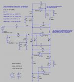
As requested, here’s a servo offset controlled amplifier I’m using. Everything but the models is zipped up in the file public-servo.zip. The servos (U3 and U4) can’t meaningfully be separated from the amps that they control, so you get the entire circuit, which is a balanced Superbal stage (U1 and U2).
The basic Superbal amplifier stage uses U1 as the difference amplifier, along with R1, R2, R5, and R6. U2 is the inverter amplifier along with R3 and R4. C7 and C9 stabilize U1 and U2, and C8 is added to re-balance the HF common mode input impedance at nodes IN+ and IN-.
The DC error at node OUT- is sensed by R11 and sent to U3, a non-inverting integrator with R11 = R12 = 66K5Ω and C4 = C5 = 100nF. This integrator lowpasses the OUT- signal with R11 and C4 before U3 sees the signal, minimizing the potential for HF distortion from U3.
The ADA4522-2 is known as a ‘zero drift’ amplifier, since it uses HF switching inside of the amplifier to cancel its internal DC offset. In doing so, it also eliminates its internal 1/f popcorn noise, which can be a problem in a servo stage using typical FET input amplifiers. The penalty is that the switching action creates small but detectable output switching noise at 200kHz and above.
Using the dual ADA4522-2, this switching noise will be synchronized between U3 and U4, preventing difference tone ‘whistles’ that might actually be audible. To eliminate the rest of any such noise, R13 and C6 form a lowpass filter. This filtered servo drive signal is sent to the Superbal IN+ node via R14, whose value is scaled to define the overall highpass frequency. Again, even though this noise is low magnitude, it varies from chip to chip, and it’s easy to add an RC output filter to practically eliminate that noise at the expense of a few extra passives.
The network of R15, R16 and C10 is added to the IN- node to re-balance the input common mode impedance, which is upset by the U3 servo’s filter and force resistor. Practically, one can replace this network with a single resistor R15 to ground with only a small CMRR degradation, but the ‘correct’ circuit is shown for clarity.
The other half of the circuit is essentially the same, except that the U4 servo force resistor R10 is twice the value of the U3 servo force resistor R14. This is not an error, and this alignment results in an extremely flat differential passband response with essentially no peaks or dips, common to many servo circuits. In a balanced circuit like this, the two Superbal amplifiers can be thought of as in series, so their DC servo stages are also essentially in series, making their frequency responses influence each other. By staggering the time constants and gain factors with this 1x - 2x force resistor scaling, an ideal differential passband response results.
If you use the simulations described below, you’ll find that the V(OUT-) and V(OUT+) are less flat than V(OUT+) - V(OUT-). However, V(OUT+) is about 0.0014dB down at 20Hz and V(OUT+, OUT-) is 0.001dB down at 5.6Hz, both of which are essentially flat, and probably not obtainable with imperfect tolerance real world components. V(OUT-) has a LF peak of around 0.48dB at 1.2Hz, but is only off by 0.004dB at 20Hz, making it suitable as a single ended output if needed.
I’ve included LTspice IV simulations but out of respect to the vendors, you have to provide their models for the op amps. In the actual device, I use the ADA4522-2 and the LM4562, but the models you want are the ADA4522 and the LME49710. For the simulation to work, download them from LICENSE AGREEMENT | Analog Devices and http://www.ti.com/lit/zip/snam001, unpack the .zip file from TI and place LME49710.lib and ADA4522.cir in the same folder as the provided public-servo.asc file.
There are several simulation commands to view the overall frequency response, the time response, and the noise performance of the overall circuit. Uncomment only one of the .ac .tran or .noise files to run the simulation. I’ve also included a file public-noservo.asc file, which is just the Superbal and no servos, so you can see the effect of the servo on the total noise of the circuit.
As can be seen in the summary below, the noise of the circuit from 20-20kHz is essentially the same with or without the DC servo. From 0.1Hz to 10Hz, the servo results in +4.6dB noise compared to the LM4562 noise alone, but the total value over that band is -138dBV, compared to the 20-20kHz noise level of -118dBV, showing that the servo’s addition to the total noise is insignificant.
A summary of the behavior:
Frequency response:
V(OUT+, OUT-): Less than 0.001dB error between 5.6Hz and 35.4kHz, -3dB at 1.02Hz and 2.4MHz.
Output offset voltage:
Each output node OUT+ and OUT- settles to around 6.3µV to 6.9µV after a few seconds, but the difference between OUT+ and OUT- is extremely low, and settles with a very long time constant to ~300nV after 3K seconds. This is obviously simulator BS based on ideal components and an expected Vos and Ib value for the ADA4522, but the important point is that the individual outputs and the differential output settle to very low values, a small multiplier of the basic servo amp offset.
Output noise referred to the input:
OUT+ 20-20kHz: 1.24uV with servo, 1.22uV without servo
OUT+ 0.1-10Hz 125nV with servo, 74.5nV without servo
OUT- 20-20kHz: 1.24uV with servo, 1.22uV without servo
OUT- 0.1-10Hz: 126nV with servo, 74.5nV without servo
Best regards,
Monte McGuire
monte@alum.mit.edu
Attachments
How stable is it?
It seems to me that the compensation capacitors within the 5534 become useless when the power rails are tied the the output.
The input stage now sees most of the output as a common mode signal. The common mode frequency response will matter.
I just used this amp in a real world instrumentation amp setting where it needed to drive a small signal transformer at 70vpp. It did so happily and without oscillations. I am using a small DC-DC SMPS that puts out up to +/-390 but I set it at the low end for +/-45v.
Amazon.com: Qianson High Voltage DC-DC Boost Converter 8V-32V to +-45V-390V Adjustable ZVS Capacitor Charging Power Supply Module: Home Audio & Theater
RE DC servo
The circuit looks really interesting. I tried something similar for a phono input with a zero drift amp to correct the offset from the differential Jfets on the input. Remarkably DC coupled with the offset removed by the chopper it worked really well with no feedback problems from the really extended bass. And the zero drift amp kept the output offset around 100 uV at 80 dB of gain.
However the hiss from the zero drift was audible. I was using an older zero drift with a switching frequency in the 5 KHz region. These newer ones may work better in that application. I need to figure out how to get the cancelling working in a simple amp stage.
- Status
- This old topic is closed. If you want to reopen this topic, contact a moderator using the "Report Post" button.
- Home
- Source & Line
- Analog Line Level
- op-amp based, high-gain, high rail voltage, preamp