Thanks for the reminder Twocents. I just have run a simulation then if I have you those numbers. The brain can’t remember all the sims it has performed. ")
Yes for Bi-amping with PLLXO, this will have plenty of oomph to drive.
If you only gave Hugh these 4 transistors, he can make anything: 2N5401, KSC1845, 2SA1837, any big N channel MOSFET.
But don’t mess with the KSC1845! It’s in every amp!
Yes for Bi-amping with PLLXO, this will have plenty of oomph to drive.
If you only gave Hugh these 4 transistors, he can make anything: 2N5401, KSC1845, 2SA1837, any big N channel MOSFET.
But don’t mess with the KSC1845! It’s in every amp!
Ok X, so those values for R14 and R15 will work well then for the secondary output.
Thank you Hugh and X - the KSC1845 will stay on the bom then!
I should ask you what your PLLXO input impedance is? It’s parts of the design so you can spec it. I would suggest no lower than 4k7.
I should ask you what your PLLXO input impedance is? It’s parts of the design so you can spec it. I would suggest no lower than 4k7.
I am nowhere near that part yet X, but according to the PLLXO calculator it will probably be between 5k and 10k - so I should be ok.
Hi X, hi all
Just ordered the boards and curious to the value you used for R11 when using the AKSA Lender pre with the Aleph J you built? Reading the thread it appears altering R10 isn't the correct thing to do, but changing R11 to something around 2K would be suitable?
Secondly I see twocents has mentioned the option of two "pre outs". I was also considering this for bi-amp purposes. Here is the newbie question sorry: what would the procedure be if the input impedence to the second amplifier was different than that of the main amplifier? Reason for asking is that I am considering adding a sub with its own amp for reinforcemnt below 60Hz maybe 80Hz or so. Stereo only, not home theatre. I recently moved and the room is a different shape. It seems I have lost a small amount of low level.
Looking forward to building this. Just ordered the boards on the 14th and made other parts orders yesterday.
Thanks
Hi X, hi all
Just ordered the boards and curious to the value you used for R11 when using the AKSA Lender pre with the Aleph J you built? Reading the thread it appears altering R10 isn't the correct thing to do, but changing R11 to something around 2K would be suitable?
Thanks
vlv81, I have a similar question regarding R10/R11. I currently have a 3.9k in for R10. Twocents posted about staying with 10k at R10 and using a 2k2 at R11 to reduce gain. Would this be the way to go if I'm using the 2SA1837's with R15 at 22 Ohms and R14 at 4.7 Ohms? I am using this with my ALPHA 20 at the moment. Could I also use this as an HPA without any modifications?
Changing R11 to 2k2 is a good way to reduce gain while keeping the amount of feedback low to preserve sound stage and spatiality.
For a HPA the recommended resistor settings are here and don’t forgot to reduce Vcc to 24v:
Qnty 2 x 22R for R15 (11R) and 2.2R for R14 and use 2SA1837 (mounting on backside since pins reversed). It will work fine as HPA and preamp for Alpha 20 or Alpha B.B. with lower gain as described above.
Last edited:
Considering to build this preamp to feed a Pass ACA, but potentially feed others in the future as well (F5 and MoFo for example), so I have a few questions. Sorry, they are basic questions:
1- R10, R15, R11: Wouldn't be easier to use trim pots instead of changing resistors? Why?
2- SMD vs TH Daughter Board: Any other differences other than physical?
3- The BOM AKSA-LENDER-X-MB_PL_04_01_2018 has a few lines defined as option. If you don't take that option, you just leave the space unpopulated? Any more details on what changes with that option? As example lines 15, 16, and 17. All of them are Caps that are marked option but are not shown anywhere else (as if there was a basic option and these would be the premium option)
4- Does the BOM contain the components for the on/off switch, filter and RCA selector as well?
Considering to build this preamp to feed a Pass ACA, but potentially feed others in the future as well (F5 and MoFo for example), so I have a few questions. Sorry, they are basic questions:
1- R10, R15, R11: Wouldn't be easier to use trim pots instead of changing resistors? Why?
These are critical audio path resistors and need to be high quality fixed metal thin film or carbon thin film in order to reduce distortion and not introduce unwanted third order distortion.
2- SMD vs TH Daughter Board: Any other differences other than physical?
SMD boards can sometimes achieve slightly lower distortion, but really neglible. The through hole board is needed if you wante to make it a HPA since larger 2SA1837 can be used and external heatsink can be fitted.
3- The BOM AKSA-LENDER-X-MB_PL_04_01_2018 has a few lines defined as option. If you don't take that option, you just leave the space unpopulated? Any more details on what changes with that option? As example lines 15, 16, and 17. All of them are Caps that are marked option but are not shown anywhere else (as if there was a basic option and these would be the premium option)
The options are for large film caps. If your cap does not need all the room, that’s ok, just leave it unpopulated.
4- Does the BOM contain the components for the on/off switch, filter and RCA selector as well?
Yes, but the RCA jacks are rather expensive $10/set and you need 5. Also, interconnect 8pin ribbon cable/jack has wrong solder pad on BOM. It needs to be through hole version.
The options are for large film caps. If your cap does not need all the room, that’s ok, just leave it unpopulated.
.
I'm sorry X, what do you mean by "if your cap does not need all the room"? As a beginner I understand this might be a dumb question, my apologies.
I've using the last hour to gauge the costs of this project. So far I am done with the MB components: Mouser Electronics
From the BOM I had the following changes (to consolidate all at Mouser):
0µ1/100V/MKC1860 ROEDERSTEIN C125, C127, C135, C137
became mouser item #75-MKP1837410011
WE7447017 WE WE-FI_7447017 L161
became mouser item #542-2300HT-220-V-RC
To correct the two errors on the BOM:
10k0 VISHAY/DALE R141
became mouser item # 71-CMF5510K000BEEA
20V VISHAY 1N400X
became mouser item # 821-1N4004G-KR0G
Are those substitutions allowable or I got something wrong?
Additionally, IRF610PBF is out of stock but will be back in a couple weeks. No biggie. However, mouser item # 647-UKW1J472MRD (Aluminum Electrolytic Capacitors - Leaded 63volts 4700uF 20%) won't be available in a few months. Is there any substitution recommended?
I will work on the daughter boards tomorrow. Right now I'm looking at $85 in parts.
Are those substitutions allowable or I got something wrong?
GASCo, I did not scrutinize your entire BOM, but picked up that you have too many caps on order for C122 and C132, which I think are the main input caps. You currently have the following in your cart:
505-MKP4D051007E00JS – Wima MKP4 10uF
555-RFS100V100MH4#5 – Elna Silmic II 10uF
871-B32669C3106K – Epcos 10uF
If you look at the schematic you will see that C122, C123 and C1022 are all 10uF caps – but you only need to pick one from the list of options. And in an earlier post X said that you could actually drop the 10uF to 4.7uF or even 2.2uF and preferably use a film cap here. So, you can change the Wima 10uF to 4.7uF and delete the Elna and Epcos 10uF caps from your cart, if I am not mistaken.
Furthermore, C1023 (1uF), is what they call a bypass cap and also optional. Some say it sounds better, others not. But I would keep that one in the cart.
Hope I have saved you a few $. You can PM me if you have more BOM questions.
Thanks for your sharp eyes, Twocents. All correct comments.
If you are trying to get most bang for the buck, the $0.17 10uF 35v Silmic II is tough to beat.
A 4.7uF Wima MKS is also pretty good.
Another excellent and cost effective cap is Dayton Audio 10uF 250v MKP axial film cap for $4.72:
Dayton Audio DMPC-10 10uF 250V Polypropylene Capacitor
As well as Audyn 10uF 400v MKP for $4.31:
Audyn Cap Q4 10uF 400V MKP Metalized Polypropylene Foil Crossover Capacitor
Last edited:
Thank you Two cents and X!
I am not really for the cheapest build. It's my first one so take that with a grain of salt, but what I'm looking at is the best cost benefit. I'm fine paying $4 instead of $0.10 for a component if it is well agreed that this is worth. I am a beginner but I bet there is a lot of snake oil in component picking as well. I just want to spend the money where it scientifically makes sense.
I have spent a couple more hours today refining and double checking the BOM for the Main board. Thank you for offering help, tow cents! I am still posting here because I believe this information is helpful for any beginner out there. If the forum guys think otherwise I'd be happy to take this to private messages instead.
From what I gathered from you guys' last two posts I put together this new BOM Mouser Electronics I'm trying to keep this one clean and public for the next beginner because really, this hasn't been fun. lol
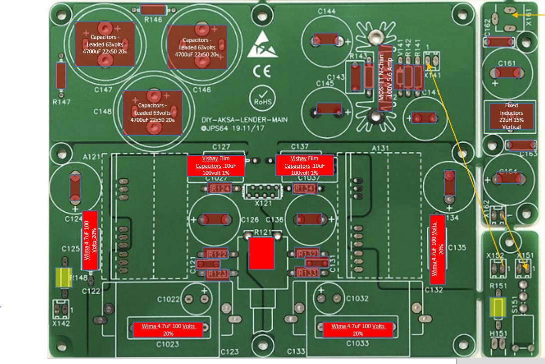
Everything is pretty straight forward for me so far, except the capacitors at the output stage. Please see the picture below where I named everything that I am not 100% sure about or that has changed from the official BOM. Will this work fine?
Questions:
1- The yellow resistors are defined as depends on V+ in the original BOM. How do I calculate them? I planning to use a white boost converter like this, unless stirred a different direction: http://www.diyaudio.com/forums/analog-line-level/314563-aksas-lender-preamp-40vpp-output-32.html#post5260733
2- That's just thinking a head, I out the yellow lines as I understand there is where G and +V are connected, is this correct? What is the connector X 142 for?
I am not really for the cheapest build. It's my first one so take that with a grain of salt, but what I'm looking at is the best cost benefit. I'm fine paying $4 instead of $0.10 for a component if it is well agreed that this is worth. I am a beginner but I bet there is a lot of snake oil in component picking as well. I just want to spend the money where it scientifically makes sense.
I have spent a couple more hours today refining and double checking the BOM for the Main board. Thank you for offering help, tow cents! I am still posting here because I believe this information is helpful for any beginner out there. If the forum guys think otherwise I'd be happy to take this to private messages instead.
From what I gathered from you guys' last two posts I put together this new BOM Mouser Electronics I'm trying to keep this one clean and public for the next beginner because really, this hasn't been fun. lol
Everything is pretty straight forward for me so far, except the capacitors at the output stage. Please see the picture below where I named everything that I am not 100% sure about or that has changed from the official BOM. Will this work fine?
Questions:
1- The yellow resistors are defined as depends on V+ in the original BOM. How do I calculate them? I planning to use a white boost converter like this, unless stirred a different direction: http://www.diyaudio.com/forums/analog-line-level/314563-aksas-lender-preamp-40vpp-output-32.html#post5260733
2- That's just thinking a head, I out the yellow lines as I understand there is where G and +V are connected, is this correct? What is the connector X 142 for?
Attachments
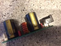
GASCo. Your posts HAVE been helpful. Like you I am new. My boards are on their way. I have already gotten the boost converter, HP SMPS and other components, such as caps etc... I was working through the option part of the BOM and schematic over the last day or two, so a timely post! Hopefully will help others decide to try this pre. Thanks also must go to the knowledgeable diyers taking the time to reply (and of course X, AKSA and JPS for making it happen in the first place)
I'm a relative noob as well but spent some time studying before I built my AKSA Lender Pre. To save a few more bucks I omitted the switch board and the CLC board (the two smaller boards on the right). The CLC board isn't really needed unless you have especially dirty power in your house. As X has said previously (paraphrasing here), an SMPS together with the built in regulated supply on the main board will already give you VERY clean power.
Also, I think your values for C125 and C135 need to be .1uF, not 4.7uF. Keep referencing the schematic when choosing your components. And triple check before you place your order. I don't know how many times I thought I had everything right only to realize after I was about to start soldering that I ordered the wrong cap or resistor.
Also, I think your values for C125 and C135 need to be .1uF, not 4.7uF. Keep referencing the schematic when choosing your components. And triple check before you place your order. I don't know how many times I thought I had everything right only to realize after I was about to start soldering that I ordered the wrong cap or resistor.
GASCo. Your posts HAVE been helpful. Like you I am new. My boards are on their way. .... I was working through the option part of the BOM and schematic .... Hopefully will help others decide to try this pre. Thanks also must go to the knowledgeable diyers taking the time to reply (and of course X, AKSA and JPS for making it happen in the first place)
I'd like to thank these guys too! It's admirable all the work and support they've given to the community.
You could use X142 with R148 for LED left side.
You could use R151 with H151 (not cheap!) on right side, or wired standard LED using jst connector instead.
JP
Aw got it now. I was lost for the schematic I just downloaded and had I had it before I'd be able to had answered myself. As those resistors are just for the LED I know how to size them.
I'm a relative noob as well but spent some time studying before I built my AKSA Lender Pre. To save a few more bucks I omitted the switch board and the CLC board (the two smaller boards on the right). The CLC board isn't really needed unless you have especially dirty power in your house. As X has said previously (paraphrasing here), an SMPS together with the built in regulated supply on the main board will already give you VERY clean power.
Also, I think your values for C125 and C135 need to be .1uF, not 4.7uF. Keep referencing the schematic when choosing your components. And triple check before you place your order. I don't know how many times I thought I had everything right only to realize after I was about to start soldering that I ordered the wrong cap or resistor.
Thanks! I will update accordingly, and now that I found the schematic (dumb me) I will follow your tips.
Anyway to know how dirty my power is, without an oscilloscope? It's only 7 bucks for the components on the CLC, but on the other hand as you say, I don't want to build it if I don't need it. I'm intending to get a meanwell PSU, would that mean by itself that the power coming from it is clean enough?
I will also omit the switch board. I was interested in the LED, but I'll jsut use the main board one through a JST connector as suggested by JPS!
Last edited:
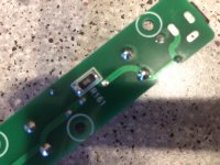
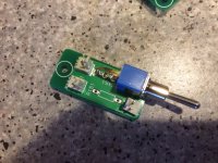
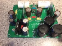
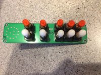
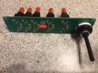
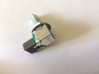
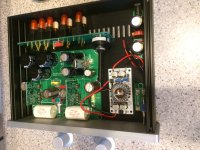
Still waiting for mechanical parts but here some fotos.
ALPS RK09 on socket to bringt it on same line as source switch.
RCA soldered with rear panel.
JP
ALPS RK09 on socket to bringt it on same line as source switch.
RCA soldered with rear panel.
JP
Attachments
-
 IMG_1641.JPG546.8 KB · Views: 160
 -
 IMG_1638.JPG549.5 KB · Views: 161
 -
 IMG_1637.JPG599.4 KB · Views: 188
 -
 IMG_1636.JPG603.8 KB · Views: 216
 -
 IMG_1634.JPG658 KB · Views: 209
 -
 IMG_1633.JPG546.3 KB · Views: 465
 -
 IMG_1632.JPG652.4 KB · Views: 475
 -
 IMG_1629.JPG282.6 KB · Views: 476
 -
 IMG_1642.JPG690.1 KB · Views: 219
- Home
- Source & Line
- Analog Line Level
- AKSA's Lender Preamp with 40Vpp Output