Nice work, Do. I see a pink Takman CF feedback resistor? Nice!
Yep, those are the Takman!
")
Just a quick question... With a 1.1V and 10K sine wave, the output measure roughly 19.5Vpp before the upper part of the sine wave starts squaring. Is this normal I'm not reaching close to 40Vpp? Just want to make sure I can drive the Mofo with plenty of power.
Thanks
Do

Hi Do,
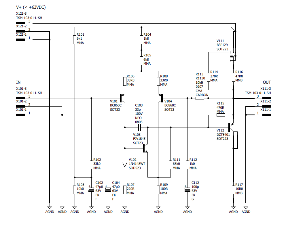
Sorry you are having troubles. That doesn’t sound right. You might have an error somewhere on the circuit. Early clipping like that sounds like maybe the resistors on the input LTP are off and the midpoint DC voltage is far from 1/2Vcc. Please check the DC voltage upstream of the output coupler. If you are clipping at 20Vpp, suggests your DC there is not 24v (1/2 of 48v) but maybe about 34v. Please check your PCB to make sure you have the correct version - I may have sent you v1 boards by mistake, which has a silkscreen typo (R102/103 we’re swapped) for the two resistors on the voltage divider that sets the input BJT bias voltage. The 33k resistor should be going to the base of Q1. If you have 10k there and 33k as the 9k1/33k divider you will have an elevated DC midpoint of 33/(33+9.1)x48v=37.6v instead of circa 24.5v. This is detailed in the errata list in Post 1 of the GB thread here:
AKSA's Lender Preamp with 40Vpp Ouput GB
Can you provide an O-scope shot like this one? This of course shows 40Vpp as demonstration that this preamp can do that.
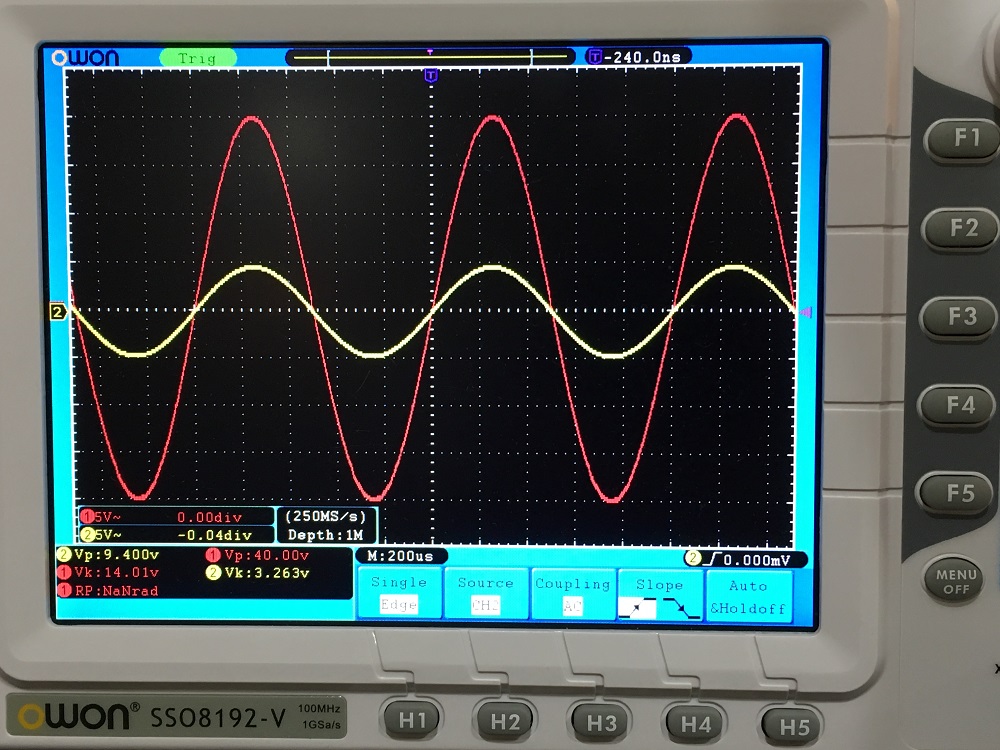
Btw, MOFO is about a 12wrms amp or needs 28Vpp to hit clipping on the amp. 40Vpp is to get to 25wrms at 8ohms.
If I accidentally sent you the wrong PCBs, please accept my apologies. I’ll send you a new set of v2’s to have for the future.
Sorry you are having troubles. That doesn’t sound right. You might have an error somewhere on the circuit. Early clipping like that sounds like maybe the resistors on the input LTP are off and the midpoint DC voltage is far from 1/2Vcc. Please check the DC voltage upstream of the output coupler. If you are clipping at 20Vpp, suggests your DC there is not 24v (1/2 of 48v) but maybe about 34v. Please check your PCB to make sure you have the correct version - I may have sent you v1 boards by mistake, which has a silkscreen typo (R102/103 we’re swapped) for the two resistors on the voltage divider that sets the input BJT bias voltage. The 33k resistor should be going to the base of Q1. If you have 10k there and 33k as the 9k1/33k divider you will have an elevated DC midpoint of 33/(33+9.1)x48v=37.6v instead of circa 24.5v. This is detailed in the errata list in Post 1 of the GB thread here:
AKSA's Lender Preamp with 40Vpp Ouput GB
Can you provide an O-scope shot like this one? This of course shows 40Vpp as demonstration that this preamp can do that.
Btw, MOFO is about a 12wrms amp or needs 28Vpp to hit clipping on the amp. 40Vpp is to get to 25wrms at 8ohms.
If I accidentally sent you the wrong PCBs, please accept my apologies. I’ll send you a new set of v2’s to have for the future.
Last edited:
Hi X,
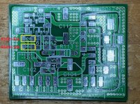
If indeed I’ve got v1 melf PCBs, could you post a picture indicating on the PCB where R102/103 are? I will just swap them back. Sorry, I cannot see the silkscreen anymore as all parts are soldered.
In the meantime, I can post a scope shot but looks like I definitely have v1 melf due to very early clipping.
Do
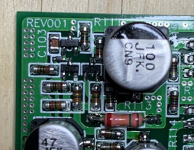
Looking at picture I posted in the link below, it clearly states REV001
AKSA's Lender Preamp with 40Vpp Output
AKSA's Lender Preamp with 40Vpp Output
Hi Do,
It has been about 3 years since we last worked on these MELF boards so I am a bit fuzzy on the whole thing myself. I am looking at the REV001 board under a mircroscope and see that the R102 correctly goes to the base of the input LTP and R103 goes to ground. R102 needs to be 33k and R102 needs to be 10k. So can you check your board to see which resistors you have at R102 and R103? Here is a graphic to show you.

Here is the schematic:
I can't quite make out the colors (MELF resistors have terrible color contrast with the brown body, and the red is almost brown rather than red, but black is clearly black) but it looks like you may have 10k and 33k resistors swapped by accident:

It has been about 3 years since we last worked on these MELF boards so I am a bit fuzzy on the whole thing myself. I am looking at the REV001 board under a mircroscope and see that the R102 correctly goes to the base of the input LTP and R103 goes to ground. R102 needs to be 33k and R102 needs to be 10k. So can you check your board to see which resistors you have at R102 and R103? Here is a graphic to show you.
Here is the schematic:
I can't quite make out the colors (MELF resistors have terrible color contrast with the brown body, and the red is almost brown rather than red, but black is clearly black) but it looks like you may have 10k and 33k resistors swapped by accident:
Attachments
Last edited:

Hi Do,
The BOM is indeed wrong. R102 needs to be 33k and R103 needs to be 10k, per the schematic. When in doubt, the schemtic overules the BOM.
Sorry about that - I need to put a note in Post 1 about this error.
Hope it is not too much of a pain to swap - some hot air and tweezers and you should be good to go.
Cheers,
X
Hi X,i think,if memory serve well,that is another error on the main board this time.Hi Do,
The BOM is indeed wrong. R102 needs to be 33k and R103 needs to be 10k, per the schematic. When in doubt, the schemtic overules the BOM.
Sorry about that - I need to put a note in Post 1 about this error.
Hope it is not too much of a pain to swap - some hot air and tweezers and you should be good to go.
Cheers,
X
R141=10k,not 220R.
Yes. And that is well documented on the errata list on post 1 of the GB thread:
AKSA's Lender Preamp with 40Vpp Ouput GB
AKSA's Lender Preamp with 40Vpp Ouput GB
Alert - error on main PCB. R141 Should be 10k not 220R.
Alert - error on main PCB diode V141 should be standard 1N400X not breakdown or zener.
Revised BOM for MB (8-pin connector was incorrect), file here:
Error 404 - Forum Page Missing
Mainboard schematic looks like this (note R141 is 10k not 220R):


Excellent Do!
At least it was just a quick resistor swap
Yeah, it wasn’t a big deal. At least the BoM is fixed now.
My friend is asking me if there’s other buffer amplifier that could work well with the AKSA Lender setup with 27dB gain and 40Vpp. He’s looking into class AB amplifier to replace the Mofo in hot summer days. If anyone knows it would be great. I only know Class A designs as buffer amps.
Thanks
Do
Thanks
Do
- Home
- Source & Line
- Analog Line Level
- AKSA's Lender Preamp with 40Vpp Output