The slew equation SR = 2pifV relates only to voltage output and frequency. If you can hear to 20KHz and say up to 10Vpeak (HF is far lower level than bass) I think a 10V/uS is enough BUT if you can get it higher without bringing up odds over evens, it should not do any harm!
Hugh
Hugh
I have wanted to change it for a long time but I have always believed that a high slew-rate was better for orchestras. Am I wrong?
I agree but not always. You can use high dynamic range recording, please notice when low SPL passage change suddenly to high SPL passage and otherwise.
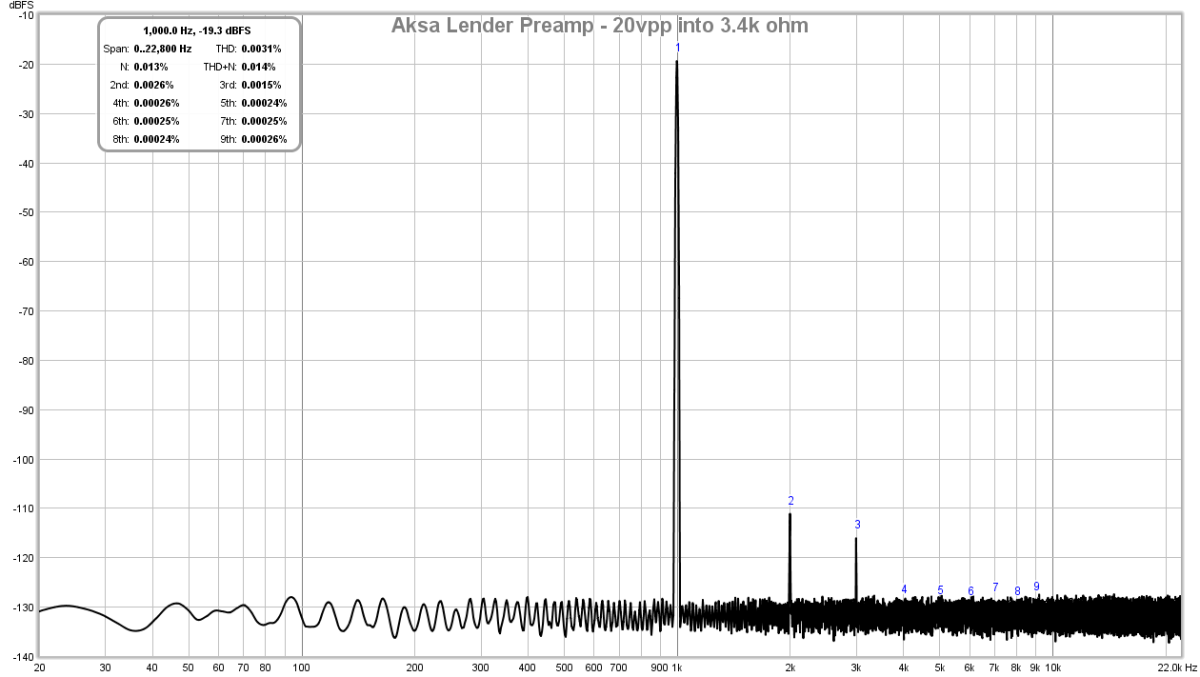
XRK, thanks for the extra lower impedance measurements.
Dan.
You are welcome. Do you find that the performance at 3.4k is suitable for your application?
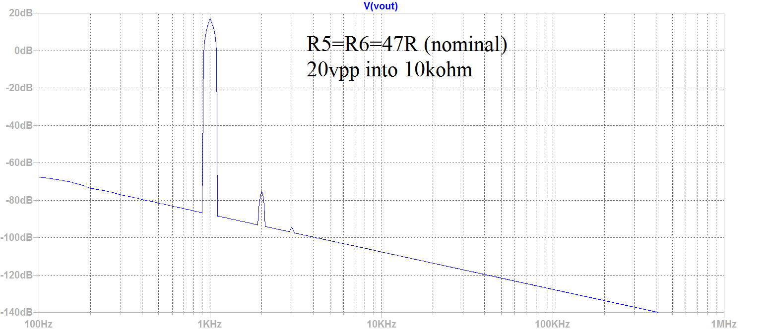
Effect of LTP Degeneration Resistors
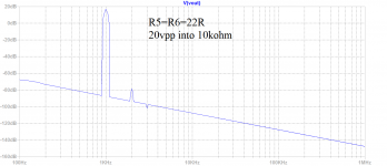
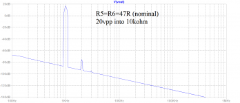
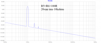
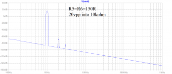
For those who may want to fine-tune the H3/H4 harmonic profile to their taste, here is what happens when the degeneration resistors of the LTP (R5 and R6) are varied from: 1R, 22R, 47R (nominal), 100R, and 150R. This is for 20v p-p into 10kohm load.
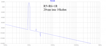
1R:

22R:

47R(nominal):
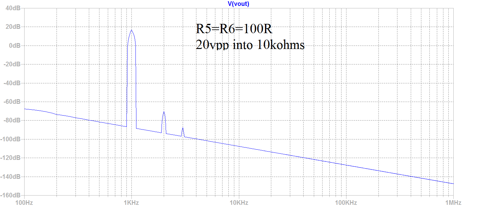
100R:
150R:
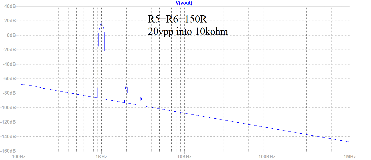
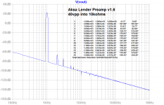
Here are the relative distortion components for the 150R case:
Just another knob there for users to fine tune to taste, whatever that may be.
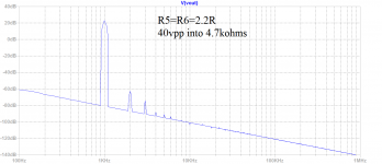
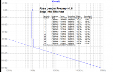
We can also use this knowledge to fine tune the response for a lower impedance load of 4.7k driven to 40vpp and still have a monotonically decreasing harmonic distortion profile by making R5=R6=2.2R:

For those who may want to fine-tune the H3/H4 harmonic profile to their taste, here is what happens when the degeneration resistors of the LTP (R5 and R6) are varied from: 1R, 22R, 47R (nominal), 100R, and 150R. This is for 20v p-p into 10kohm load.
1R:
22R:
47R(nominal):
100R:
150R:
Here are the relative distortion components for the 150R case:
Harmonic Frequency Fourier Normalized Phase Normalized
Number [Hz] Component Component [degree] Phase [deg]
1 1.000e+03 9.992e+00 1.000e+00 0.07° 0.00°
2 2.000e+03 6.125e-04 6.130e-05 96.23° 96.16°
3 3.000e+03 9.096e-05 9.104e-06 5.15° 5.09°
4 4.000e+03 1.521e-05 1.522e-06 -161.88° -161.95°
5 5.000e+03 1.209e-05 1.210e-06 -178.67° -178.74°
6 6.000e+03 9.770e-06 9.778e-07 179.88° 179.81°
7 7.000e+03 8.345e-06 8.352e-07 179.88° 179.81°
8 8.000e+03 7.299e-06 7.305e-07 -179.99° -180.05°
9 9.000e+03 6.492e-06 6.498e-07 -179.97° -180.04°
10 1.000e+04 5.844e-06 5.848e-07 -179.99° -180.06°
11 1.100e+04 5.312e-06 5.316e-07 -179.99° -180.06°
12 1.200e+04 4.869e-06 4.873e-07 -179.99° -180.06°
13 1.300e+04 4.495e-06 4.498e-07 -179.99° -180.06°
14 1.400e+04 4.174e-06 4.177e-07 -179.99° -180.06°
15 1.500e+04 3.895e-06 3.899e-07 -179.99° -180.06°
Total Harmonic Distortion: 0.006203%(0.008600%)
Just another knob there for users to fine tune to taste, whatever that may be.
We can also use this knowledge to fine tune the response for a lower impedance load of 4.7k driven to 40vpp and still have a monotonically decreasing harmonic distortion profile by making R5=R6=2.2R:
Attachments
-
 Lender-Preamp-Aksa-FFT-20vpp-Degen-1R.png28.5 KB · Views: 1,550
 -
 Lender-Preamp-Aksa-FFT-20vpp-Degen-22R.png29.7 KB · Views: 1,538
 -
 Lender-Preamp-Aksa-FFT-20vpp-Degen-47R.png30.2 KB · Views: 1,536
 -
 Lender-Preamp-Aksa-FFT-20vpp-Degen-100R.png43.6 KB · Views: 1,546
 -
 Lender-Preamp-Aksa-FFT-20vpp-Degen-150R.png30.7 KB · Views: 1,549
 -
 Lender-Preamp-Aksa-FFT-40vpp-4,k7-Degen-2.2R.png30.3 KB · Views: 1,492
Last edited:
I received this "modest suggestion" via a PM, from a member whom appears to be on the DIYA-self-imposed-exile-island:

Looks nice, but all FETs...
From the author
I will post this for the author this one time because I am trying to be open to all suggestions and comments. However, this is a hassle and if you have more to say please reply directly to thread.
Looks nice, but all FETs...
From the author
Open Loop gain is 56dB with a >100kHz -3dB point. So global loop NFB is a substantial 37dB.
At 4V PP into 3.4kOhm (see original thread why this) the sim suggests 0.0003% THD (pretty much pure H2) which is maintained at 10kHz and rises only 8dB at 100kHz to 0.00075% (still mainly H2).
At 36V PP into 3.4kOhm it looks like 0.005% THD (h2 dominant but higher order stuff creeps in) with 0.01% at 100kHz.
I will post this for the author this one time because I am trying to be open to all suggestions and comments. However, this is a hassle and if you have more to say please reply directly to thread.
Last edited:
X I'm looking at your latest simulations, am wondering what does it mean when some of the harmonics goes negative as in the R5=R6=1Ohm and 22Ohm cases where the H3 takes a dive.
They are not negative, it's a log plot so can't go negative - the value is just lower than the descending (due to 1/f) average baseline. If that makes sense.
Last edited:
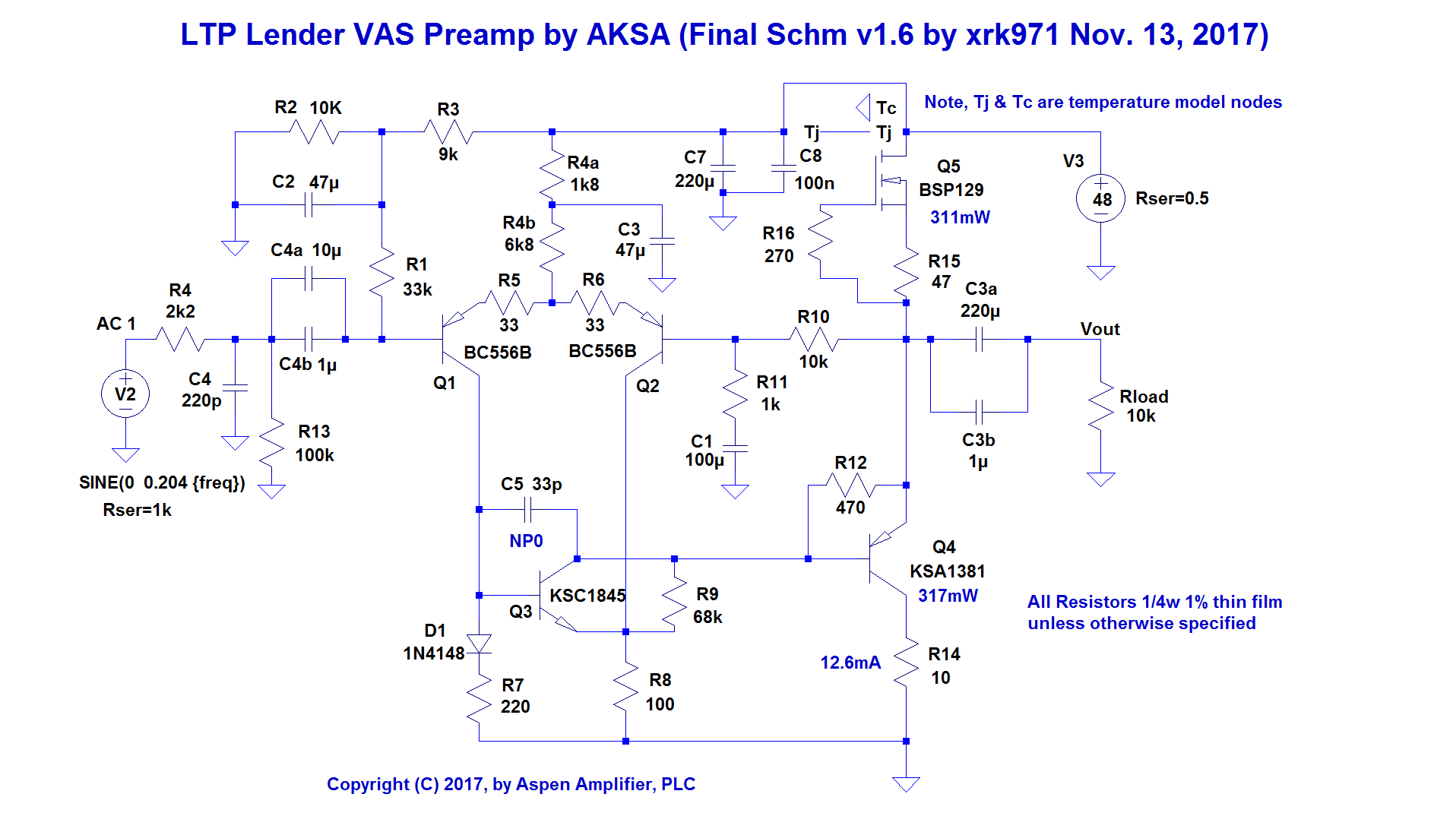
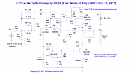
Some final tweaks v1.6
I think the preamp is ready for layout and production. I added an RF filter on the input, adjusted the degeneration resistor to 33R for reduced distortion at 40vpp, although this is totally user adjustable from 0R to 220R depending on how much thickness/body/sweetness one likes the sound to have. I also added a decoupling cap for the LTP as suggested by Juma. The BSP129 and KSA1381 are both dissipating about 300mW ea so can work without any extra heatsinking. If you push the bias current above 12mA, make sure to add a heatsink or extra copper pad for BSP129. All resistors are usual 1/4w axial and preferably 1% metal thin film on R5 and R6 to assure balance. Use 5% carbon composition resistors where you think it makes sense in signal path if value not critical. Match the Hfe of the Q1 and Q2 for lowest distortion. Use a high quality electrolytic such as Elna Silmic II on C4a, and likewise on C3a, use a decent brand name 50v electrolytic.
Here is final schematic v1.6:
Here is predicted FFT for 4vpp into 10kohm (0.00055% THD):

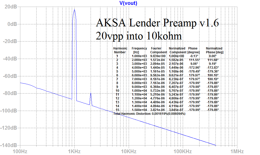
Here is predicted FFT for 20vpp into 10kohm (0.0016% THD):
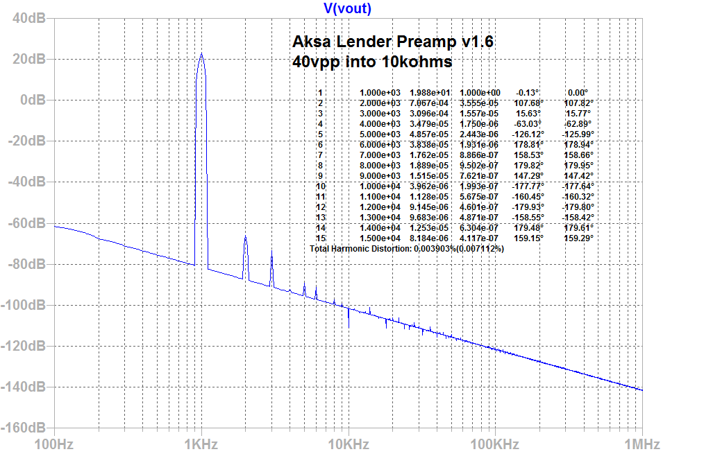
Here is predicted FFT for 40vpp into 10kohm (0.0039% THD):
I think the preamp is ready for layout and production. I added an RF filter on the input, adjusted the degeneration resistor to 33R for reduced distortion at 40vpp, although this is totally user adjustable from 0R to 220R depending on how much thickness/body/sweetness one likes the sound to have. I also added a decoupling cap for the LTP as suggested by Juma. The BSP129 and KSA1381 are both dissipating about 300mW ea so can work without any extra heatsinking. If you push the bias current above 12mA, make sure to add a heatsink or extra copper pad for BSP129. All resistors are usual 1/4w axial and preferably 1% metal thin film on R5 and R6 to assure balance. Use 5% carbon composition resistors where you think it makes sense in signal path if value not critical. Match the Hfe of the Q1 and Q2 for lowest distortion. Use a high quality electrolytic such as Elna Silmic II on C4a, and likewise on C3a, use a decent brand name 50v electrolytic.
Here is final schematic v1.6:
Here is predicted FFT for 4vpp into 10kohm (0.00055% THD):
Here is predicted FFT for 20vpp into 10kohm (0.0016% THD):
Here is predicted FFT for 40vpp into 10kohm (0.0039% THD):
Attachments

Last edited:
I personally use a circa 1 amp 12v SMPS that feeds a DC-DC step up boost module to 44v to 48v, then run that through a CRCRC filter (4.7mF & 0.33R's with 330pF + 10R snubbers and 0.1uF 100v film bypass caps). With this, I get the absolutely flat-as-a-board noise floor devoid of any mains peaks/bumps as you can see.
But the choice of SMPS and DC step up makes a difference. The "Vonage" brand 12v SMPS from an old Lepai amp works well. Use the blue PCB 7 to 10 amp capable DC boost/buck modules with dual heatsinks. They are much more quieter than the smaller ones without big heat sink fins.
Here is an example of the spectrum devoid of 60Hz/120Hz/180Hz mains hum peaks:
Last edited:
I received this "modest suggestion" via a PM, from a member whom appears to be on the DIYA-self-imposed-exile-island:
.
This design is a good (and very clever) attempt to use a similar topology but it has one issue - MOSFETs when used as a common source in the VAS lack depth of imaging, and this is something that is only audible from listening. They work great as source followers, but not in common source if depth of imaging is important. Otherwise a very nice design. Also, I don't like MOSFETs in the VAS if it is avoidable due to larger parasitic capacitances. Alternatively, a KSC1845 is wonderfully and almost perfectly suited for the job here insteadnof T3.
This is simpified generalization, F5 and some other amps use mosfets in common source...MOSFETs when used as a common source in the VAS lack depth of imaging, and this is something that is only audible from listening. They work great as source followers, but not in common source if depth of imaging is important.
This is simpified generalization, F5 and some other amps use mosfets in common source...
Specifically in the VAS is where it affects imaging. I don't believe F5 had a MOSFET in the VAS stage. ZTX BJT if I recall controls bias and JFETs drive output stage gates directly in push-pull.
Last edited:
Specifically in the VAS is where it affects imaging. I don't believe F5 had a MOSFET in the VAS stage. ZTX BJT if I recall controls bias and JFETs drive output stage gates directly in push-pull.
If you "don't belive" in that, then I'm not so shure that you know what you are talking about. Bjts in F5 are not for biasing and the output stage mosfets are in common source , so they are also used for vas (voltage amplifier stage).
My mistake, I have built Juma's F5 which did not use ZTX BJT and went straight from JFET to MOSFET gate...
Yesterday I heard your fourteen amplifiers and I loved the F5 Juma sound.
Virtual Audition of Very Simple Quasi MOSFET Amp
Maybe the 15th would be the Cubie3
- Home
- Source & Line
- Analog Line Level
- AKSA's Lender Preamp with 40Vpp Output