Smoke
Made some smoke last night. I bypassed the DC step-up converter with small jumper cables (those ones with crocodile clips) from a 24V smps. These cables are very thin, but the one (the ground) started to melt and actually caught alight! I immediately yanked off the cables, switched everything off and packed up for the night. This tells me that there is a short somewhere on the board.
Thinking about my sins this morning, I realized that I made a dumb dumb dumb mistake. In my haste I never fitted the plastic collar to the bolt on the IRF610 (of the cap mx) to the heatsink, so the mosfet is probably making a short to ground. I have not tested this theory, but assume that I popped the mosfet in the process. Replacing this mosfet will require quite a delicate operation. Damn. Guess it’s part of diy.
So X, your feeling was correct - my cap mx is not working.
Your MOSFET is probably ok. Since the tab is the drain connected to the power input. The current never went through the MOSFET active - just straight to ground (assuming your heatsink is soldered to the ground connection). You can check to see if mosfet works simply by adding the insulator bushing(washer).
Remove the daughter boards so we can see if the power is produced after the cap Mx all the way to the final set of smoothing caps at the base of the daughter board edge connector. It should be about 3.5v to 4.5v less than DC step up.
Short fixed and thank goodness no damage. And yes you are correct X - the mosfet (IRF610) is still fine and it seems like the Cap Mx is also working correctly. However, there still seems to be a problem as I am getting strange measurements (without daughter boards). The picture shows an unpopulated board, but with the points where I made some quick measurements. Left and right is different, so it could be incorrect polarity on one of the caps maybe? I will have to lift the board from the enclosure since most of the electrolytics are mounted underneath to make space for the daughterboards and biggish heatsinks. Will post more photos later if I still cannot find the problem.
Attachments
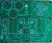
Short fixed and thank goodness no damage. And yes you are correct X - the mosfet (IRF610) is still fine and it seems like the Cap Mx is also working correctly. However, there still seems to be a problem as I am getting strange measurements (without daughter boards). The picture shows an unpopulated board, but with the points where I made some quick measurements. Left and right is different, so it could be incorrect polarity on one of the caps maybe? I will have to lift the board from the enclosure since most of the electrolytics are mounted underneath to make space for the daughterboards and biggish heatsinks. Will post more photos later if I still cannot find the problem.
Don’t worry about odd voltage on pin 9 (top one) that’s just the residual voltage you are measuring on the output cap.
Measure pin 6 and that should be same as 44.5v.
I think you are good to go.
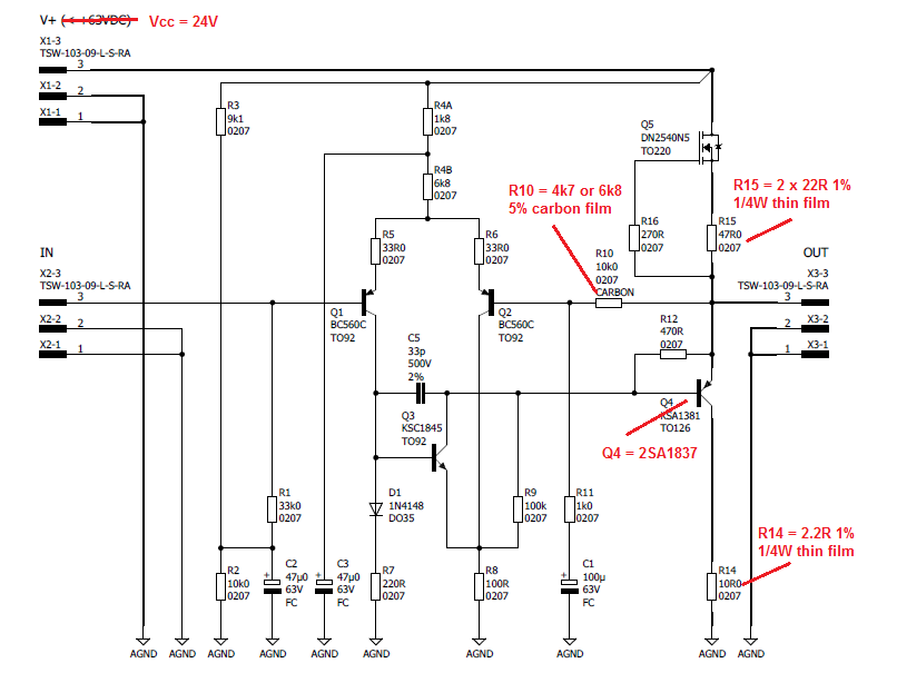
Yes, some good news and bad news. The Lender is (sort of) working, but I am very confused here about the bias. I measure 8V across R10 (10k) on both channels – is this normal? The problem is that the Lender seems to have less (or same) gain than my B1 driving the ACA. My Lender is stock standard except for:
Q4 = 2SA1837 (iso KSA1381)
R11 = 2k2 (iso 1k0), could 2k2 be way too much for R11?
The other problem I have is with this el cheapo 23 step attenuator - it is the biggest piece of rubbish I ever bought on Ali. It makes the most horrendous shorts while turning. Should have used the money on brighter color input caps. I saw some nice purple ones earlier in the thread.
Attachments
Hi Twocents,
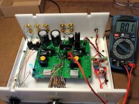
Nice looking case!
Don’t worry, we will figure this out - there are no fragile parts except the DN2540 which can get zapped by ESD.
You can debug the daughterboards outside of main board on the bench with alligator clips to the power pin and ground pin to check and set bias etc.
If you measure correct bias outside on bench. It will work correctly.
Two places to check bias: the main outputs at R15 as you said. And also check bias of LTP at either R4A or R4B.
If using 2SA1837 - this is the HPA mod, increase bias current (from 20 to 100mA) by changing R15 to 11ohms 2 x 22 ohm 1/4w in parallel or use 10ohm 1/2w resistor. Decrease Vcc at amp (after cap Mx to 24v). If not enough gain change R11 back to 1k. Drop R14 to 2R2. Is R10 set at 10k?
Either way, 5x gain would have added 14dB gain - way more than 0dB of B1. Looks like your Preamp was not working and it may have been incorrect bias for upgraded 2SA18237.
I see a lot of missing electrolytic caps - are they mounted on the bottom side?
The mods for the HPA are detailed here:
Aksa Lender HPA
Last edited:
Hi guys
Twocents, it looks like you have gone for two pre outs. If this is the case is it possible this may have the effect of seemingly reducing the gain?
I was reluctant to post this because of my poor understanding of whats happening in the circuit, but remebered that both you and I had considered doing this earlier in the thread and thought this could be an issue. Apologies if not, just a newb suggestion
Hey vlv81, don't be reluctant to ask noob questions. I am a nervous novice here too.
Yes, I have made provision in the box for two pre outs, however I did not implement the suggested resistor changes (yet). I first want to get it to work with what I have. The secondary output detail is in this post: AKSA's Lender Preamp with 40Vpp OutputTwocents, it looks like you have gone for two pre outs. If this is the case is it possible this may have the effect of seemingly reducing the gain?
This is great and will be very helpful thank you. Btw, alligator clips are called crocodile clips in Africa (and maybe also Down Under where Hugh is) – I think they have bigger teeth.You can debug the daughterboards outside of main board on the bench with alligator clips to the power pin and ground pin to check and set bias etc.
If you measure correct bias outside on bench. It will work correctly.

Just to clarify – I would like to get the Lender working as a preamp to drive my ACA. I am not interested in the HPA mod or use for now. I just thought the Toshiba would be an improvement. Hence I have two options (as you detailed):
1) Keep the 2SA1837, but increase the bias and drop Vcc to 24V, or
2) Replace 2SA1837 with the original KSA1381 as intended and leave everything else as is.
I am reminded of what you suggested in Post 598 – “if you want to drive a MoFo or F4 at high voltage swing stick with the lower bias current and KSA1381 and 48v supply.”
So, I am thinking option2 is the best here?
PS: Thank you for all your hand holding, advice and encouragement X. Don’t know where you always find the time for posts between work, family, sleep and the occasional domestic disaster? Have a break and take your wife on a date night for a change. We will miss you here, but hey, what is a day or two without your posts between friends.
There is an amp called a BiB?
I was trying to figure out what BiBs was also!
Finally finishing measurements after fixing my hum problem: R3 and R4A wrong equipped.
This preamplifier could be builded from the box and no problems to expect.
Today listening session with first setup consisting of PC, foobar, ifi nano iDSD, EL34 SE, Greencone Rondo. MoFo, ACA, M2 still in pipeline (writing assembling instruction with 3D view during construction) for the next setups.
I´ll publish for the weekend complete and detailled test report.
JP
In the mean time I have been reading a bit about pots and came upon the following interesting post. Someone asked about a good 10K pot and the answer was:
Can this arrangement work in the Lender? Is the impedance not too high?
The best ~ 10K pot is a ~ 100K linear with an ~ 15K for pseudologarithmic.
Can this arrangement work in the Lender? Is the impedance not too high?
I’m not good at waiting. Waiting for the KSA1381s to arrive. Everything is ready and done – only need the KSAs – only 6 soldering joints and my Lender will be finished. Ironically it was easier and faster to source the Toshiba 2SA1837s (and even 2SK170s) locally, than the KSAs! RS sells them, but minimum qty 60. I buy less and less from RS, they just don’t cater well for hobbyists.
I also chucked out the stupid attenuator and replaced it with a 10K (and 1K2 loading resistor) linear Bourns pot – will see (or hear) how it works. Cannot wait.
We are also waiting for JPS64’s listening impressions. No pressure JP.
I also chucked out the stupid attenuator and replaced it with a 10K (and 1K2 loading resistor) linear Bourns pot – will see (or hear) how it works. Cannot wait.
We are also waiting for JPS64’s listening impressions. No pressure JP.
If you are tired of waiting, the 2SA1837 may work if you boost the bias a bit more. Sorry these things can really take long. That’s something I could have sent you with the original PCB had you known you needed it. KSA1381 is common $0.38 part with 5400 in stock at Mouser.
- Home
- Source & Line
- Analog Line Level
- AKSA's Lender Preamp with 40Vpp Output