i just need to specify an rc filter that works with the minidsp and the amp with the lowest attenuation possible.
The output impedance is 560R, so 2.5k for the series R
gives 1.53Vrms (-2.3dB) output with a load of 9.9k.
If we depend on the 560R output impedance only, with no extra series resistor,
then 2Vrms input gives 1.89Vrms output (-0.49dB).
The low pass capacitor would then go in parallel with the amplifier input.
Last edited:
I like the sound of using the output impedance, less attenuation to deal with. Are there drawbacks to this approach?
One other question: surely the output impedance is already considered? I. E. The output will be 2v *after* the 560R output impedance, so attenuation would be zero?
Thanks for the great help.
One other question: surely the output impedance is already considered? I. E. The output will be 2v *after* the 560R output impedance, so attenuation would be zero?
Thanks for the great help.
the output voltage or emf is 2V, the source impedance is 560ohms..................... surely the output impedance is already considered? I. E. The output will be 2v *after* the 560R output impedance, so attenuation would be zero?
Thanks for the great help.
If you feed that output to an infinitely high load impedance the load sees the full 2V of output.
If you feed the output to a 560ohms load, then the emf gets split exactly into two equal parts.
1V is dropped through the internal source impedance and the other 1V is dropped across the load.
the output voltage or emf is 2V, the source impedance is 560ohms.
If you feed that output to an infinitely high load impedance the load sees the full 2V of output.
If you feed the output to a 560ohms load, then the emf gets split exactly into two equal parts.
1V is dropped through the internal source impedance and the other 1V is dropped across the load.
right. I think i actually understand! Thanks for the basic lesson
")
So this means, given the 9.9k input impedance of the amp and the 560R output impedance of the dsp, and the 2v rms output, the voltage i will see across the amp input will only ever be 1.89v. Rms.i think I can live with that.
Yes, the 1.89Vac from a 2Vac source. That's a loss due to the 560r of 0.48dB
Yes, 3.16kHz for 560r & 90nF
Instead use 100nF with 510r (3.12kHz) or 470r (3.39kHz) or paralleled 1000r (3.18kHz)
or 510r||39k (3.16kHz)
or keep the 560r with 100nF and add an adjusting resistor to give the F-3dB frequency you require.
Yes, 3.16kHz for 560r & 90nF
Instead use 100nF with 510r (3.12kHz) or 470r (3.39kHz) or paralleled 1000r (3.18kHz)
or 510r||39k (3.16kHz)
or keep the 560r with 100nF and add an adjusting resistor to give the F-3dB frequency you require.
I like the sound of using the output impedance, less attenuation to deal with.
The output will be 2v *after* the 560R output impedance, so attenuation would be zero?
The output impedance is probably just a series 560R resistor at the output.
Using it only will probably work.
The rated 2V output is usually the either open circuit voltage, or the voltage
into a 10k load, so it should be ok.
.
Last edited:
The output impedance is probably just a series 560R resistor at the output.
Using it only will probably work.
The rated 2V output is usually the either open circuit voltage, or the voltage
into a 10k load, so it should be ok.
.
Well the components around the output of the minidsp are all tiny surface mount. Black is usually resistor right?
Seems to be one in series directly before output.
No actual markings or identification to get a brand i can see. I guess i will finish my build, add a 90 nf or thereabouts capacitor across amp input, and measure response. Ive got a minidsp and measurement microphone after all
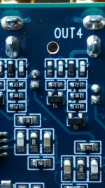
The resistors are the ones below, with white markings. Looks like there is a LCLC filter before the output. Plain black is usually inductor or ferrite bead.
But before that, you have two 270R resistors in serie with the output, with a muting transistor in between. That's your 540R output impedance, plus some resistance in the inductors or ferrite afterwards.
But before that, you have two 270R resistors in serie with the output, with a muting transistor in between. That's your 540R output impedance, plus some resistance in the inductors or ferrite afterwards.
can you tell of the 4 digit resistors are 2 sig fig plus a multiplier (number of zeros)?
or as written with 3 sig fig.
Are the 4 digit resistors 3 sig fig plus multilpier?
Im not sure if that was directed at me? Not a clue im afraid, if so :/
typo, note to self. Must try harder.can you tell of the 4 digit resistors are 2 sig fig plus a multiplier (number of zeros)?
or as written with 3 sig fig.
Are the 4 digit resistors 3 sig fig plus multilpier?
should have said:
can you tell if the 3 digit resistors are 2 sig fig plus a multiplier (number of zeros)?
or as written with 3 sig fig?
Are the 4 digit resistors 3 sig fig plus a multilpier?
Why does it matter ? From the output pin of the opamp, you've got only those two "271" resistors in serie with the output. Whatever the marking code, the value is the same.
There's a "30c" resistor to gnd after the coupling cap, that's 20k, but it doesn't affect the output impedance. The "511" is clearly tied to the muting transistors, not important either.
The "1502" and "2002" are in the feedback loop of the opamp and aren't relevant either.
There's a "30c" resistor to gnd after the coupling cap, that's 20k, but it doesn't affect the output impedance. The "511" is clearly tied to the muting transistors, not important either.
The "1502" and "2002" are in the feedback loop of the opamp and aren't relevant either.
ok so i thought i had got this all sorted.. then, in bed last night (ok it took me ages to sleep) i realised something which means either i dont understand properly, or i have a major design issue.
if i connect a capacitor across the input of one of the amps, its electrically equivalent of connecting it across both amp inputs, since they would be wired in parallel to the dac/minidsp output.. so id lose the high end from both amps...?
i assume wiring them in parallel to the dac output is the way to run two amps from one dac output? obviously that would present the dac with a 5kohm impedance rather than 10kohm.. again, a problem? or no?
basically how on earth do i connect two amps to a single source, and lowpass one of them?
also, and testing my understanding here: if the cap appears as a short circuit at higher frequencies, is there a risk to the minidsp output?
how on earth do i connect two amps to a single source, and lowpass one of them?
Then you still have to use a series resistor to the low pass amp, and then the capacitor after it.
Last edited:
so adding a series resistor before the capacitor on the "leg" of the y split that goes to the amp to be lowpassed, will avoid lowpassing the other amp? i assume id also have to add a matching resistor to the other leg to match the gain between the amps.
so im back to the issue of reduced amp gain... to be honest i wonder wether its worth it in the end. maybe the effect of a single point source for the high frequencies (as opposed to two fullrangers) isnt worth the loss of gain due to lowpass, or amp modification to increase gain.
so im back to the issue of reduced amp gain... to be honest i wonder wether its worth it in the end. maybe the effect of a single point source for the high frequencies (as opposed to two fullrangers) isnt worth the loss of gain due to lowpass, or amp modification to increase gain.
i assume id also have to add a matching resistor to the other leg
to match the gain between the amps.
Yes, the other path should have an equal series resistor to match the gains.
This is the best you can do with a simple passive circuit.
but, given an arbitrary resistance added ( i.e. as low as i can get away with) will i not still get some percentage of high frequency loss on the other amp? to my mind only an infinite resistance would eliminate the lowpass affecting the other amp, but i could be completely mistaken.
but, given an arbitrary resistance added ( i.e. as low as i can get away with) will i not still get
some percentage of high frequency loss on the other amp? to my mind only an infinite resistance
would eliminate the lowpass affecting the other amp, but i could be completely mistaken.
Now you're getting into the details. Yes, there will be some coupling between the paths due to the
common 560R output resistance, and this will cause a rolloff in the other path to a degree that is
related to the ratio of 560R to the value of the added series resistor. This coupling can only be
avoided by adding an active buffer with a very low output impedance to minimize this coupling.
Last edited:
- Status
- This old topic is closed. If you want to reopen this topic, contact a moderator using the "Report Post" button.
- Home
- Source & Line
- Analog Line Level
- RC filter component selection