Hi,
I recently got myself an ebay board with NE5532 chips as preamps.
New NE5532 Stereo Pre-amp Preamplifier Tone Board Audio 4 Channels Amplifier MO
I'm facing the issue that the pre-amp is causing too much signal gain. A passive pre-amp has too little.
I know the NE5532 or alike use capacitor/resistor values to determine the gain. Can someone help me find a combination to make its output apppropriate for a Sure AA-AB32221 board?
Sure Electronics' webstore 2 x 150 Watt Class D Audio Amplifier Board - TAS5613
Thanks a lot!
If you are unsure which resistors to change (easy but you need the circuit details to determine which) then the safest way is simply to add a low impedance attenuator to the output. The 5532 will fully drive 600 ohms and so something like two 470 ohm in series from output to ground would be a starting point. Take the output from the junction of the two and tweak the lower one up or down to raise/lower the level.
This is quite good and there's a link to a youtube video Op Amp Gain | Operational Amplifier Calculation Equations | Radio-Electronics.com
Turn the volume down on the preamp?
That would technically do it, but this wouldn't fix the issue. I would still be able to accidentally whoop the volume to the max.
If you are unsure which resistors to change (easy but you need the circuit details to determine which) then the safest way is simply to add a low impedance attenuator to the output. The 5532 will fully drive 600 ohms and so something like two 470 ohm in series from output to ground would be a starting point. Take the output from the junction of the two and tweak the lower one up or down to raise/lower the level.
And how can I determine which resistors I should be using? I don't have spare parts in drawers or alike, so I'd have to go and scavenge hunt for things. I know what a voltage devider is, and wanted to try one too, but decided it may be easier to tweak the board instead or something.
That's an operator issue, and has nothing to do with the design of the preamp. The volume control is included precisely for adjusting the gain/volume, so why do you want to make things harder for yourself, have too much time on your hands?That would technically do it, but this wouldn't fix the issue. I would still be able to accidentally whoop the volume to the max.

You can only tweak the board if you know the circuit configuration. Having a tone control on there complicates things because you could end up altering the wrong part of the circuit.
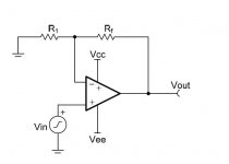
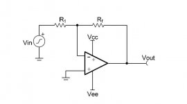
The gain follows the standard relationships as shown in the diagram depending on whether they are configured as non inverting or inverting.
Increasing R1 lowers the gain for non inverting configuration.
Voltage gain equals (Rf/R1) + 1
For the inverting stage the gain is simply Rf/R1
The gain follows the standard relationships as shown in the diagram depending on whether they are configured as non inverting or inverting.
Increasing R1 lowers the gain for non inverting configuration.
Voltage gain equals (Rf/R1) + 1
For the inverting stage the gain is simply Rf/R1
Attachments
Last edited:
A passive control would be very unusual... that's the whole point of using the opamps, it makes it so easy.
Look at any opamp data sheet that has a tone control as an illustrated application and see if it matches yours. You have a third pot for mid but the basic configuration would be the same.
Look at any opamp data sheet that has a tone control as an illustrated application and see if it matches yours. You have a third pot for mid but the basic configuration would be the same.
Try a 1K trimpot to ascertain the values you need.
I'll order a couple on ebay or ali. Might come in handy besides this project.
You can only tweak the board if you know the circuit configuration. Having a tone control on there complicates things because you could end up altering the wrong part of the circuit.
The gain follows the standard relationships as shown in the diagram depending on whether they are configured as non inverting or inverting.
Increasing R1 lowers the gain for non inverting configuration.
Voltage gain equals (Rf/R1) + 1
For the inverting stage the gain is simply Rf/R1
Oh so R1/Rf is basically also a voltage devider of which junction decides the gain of the opamp?
Last edited:
YesOh so R1/Rf is basically also a voltage devider of which junction decides the gain of the opamp?
decreasing Rf would decrease the voltage on the opamp input? In what fashion does R1 need to be adjusted?
Just like a pot? (eg if one goes up, the other goes down by the same amount)
Golden rule for any opamp connected with feedback (so all audio amps). The opamp output does whatever is needed to maintain the difference between the two inputs as zero (disregarding minute offsets and imbalances).
So for the non inverting stage...
If Rf = 9000 ohms and R1 =1000 ohms and we apply +1 volt to the input... what happens ?
In order for the two inputs to have zero difference between them the inverting input has to also equal +1 volt. In order for that to happen the output must therefor be at +10 volts.
So there is now 9 volts across Rf and 1 volts across R1. Total output voltage +10 volts.
Gain equals Vout/Vin which is 10/1 which equals 10.
Gain equals (Rf/R1) + 1 which is (9000/1000) + 1 which is 10.
Try it for the inverting configuration using the same values. What do you get ?
Decreasing Rf increases the voltage on the inverting input which decreases the gain. The op amp amplifies the difference between the inputs
That means I can parallel add a certain value resistor to decrease the value if completely removing it wouldn't do it?
Golden rule for any opamp connected with feedback (so all audio amps). The opamp output does whatever is needed to maintain the difference between the two inputs as zero (disregarding minute offsets and imbalances).
I'll fill that in tomorrow when I get back from school.
Yes, that's a way to do it. You mustn't completely remove it, that would leave it open circuit and you'd have open loop gain of the op amp which is extremely highThat means I can parallel add a certain value resistor to decrease the value if completely removing it wouldn't do it?
- Status
- This old topic is closed. If you want to reopen this topic, contact a moderator using the "Report Post" button.
- Home
- Source & Line
- Analog Line Level
- Adjusting gain on NE5532