Output is bigger than input?? (Neither "IRL" or the movie is clear.)
Then increase the "5.1K" input resistors to 10K or 20K.
Then increase the "5.1K" input resistors to 10K or 20K.
Output is bigger than input?? (Neither "IRL" or the movie is clear.)
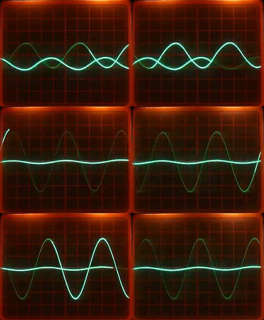
The movie is showing my scope with its two probes, one on the input and one on the output. (it should be very clear on what happens for those who have already used a scope IMHO)
Then increase the "5.1K" input resistors to 10K or 20K.
It will not change the final ratio, and i have some difficulties to think that a PFB can lower the signal.
The built in resistor between pins 8 and 10 is actually a wire-wound resistor with the two ends of it wound around the transformer core and out of phase with each other. That way it can function as a resistor rather than a transformer winding. Pin 9 is the center tap of the two out of phase windings that make up the resistor.
To a first approximation at least, it appears the purpose of the resistor winding is to make it possible for the op-amp circuit work as a balanced differential amplifier. The resistance of the winding between pins 8 and 10 matches the resistance of the winding between pins 6 and 7. The two 5k10 resistors are also matched, thus the resistances around the op-amp are symmetrical and balanced.
The gain of the circuit would appear to be a function of transformer primary to secondary winding ratio, and the effective resistances around the differential op-amp circuit that follows the transformer.
Last edited:
The built in resistor between pins 8 and 10 is actually a wire-wound resistor with the two ends of it wound around the transformer core and out of phase with each other. That way it can function as a resistor rather than a transformer winding. Pin 9 is the center tap of the two out of phase windings that make up the resistor.
To a first approximation at least, it appears the purpose of the resistor winding is to make it possible for the op-amp circuit work as a balanced differential amplifier. The resistance of the winding between pins 8 and 10 matches the resistance of the winding between pins 6 and 7. The two 5k10 resistors are also matched, thus the resistances around the op-amp are symmetrical and balanced.
Thanks for your great informations !
The gain of the circuit would appear to be a function of transformer primary to secondary winding ratio, and the effective resistances around the differential op-amp circuit that follows the transformer.
The 1:2 gain of my circuits should be a consequence of resistances mismatches ?
...Or a change in the magnetic flow that modify the winding between pins 6 and 7 ratio ?
The input signal seems to be lowered a lot when i switch on the circuit, is it not so stupid to think that the current is dominating the input winding.
The input signal seems to be lowered a lot when i switch on the circuit, is it not so stupid to think that the current is dominating the input winding.
Last edited:
Thanks for your great informations !
The 1:2 gain of my circuits should be a consequence of resistances mismatches ?
What are the resistances of the transformer windings?
If you measure them, you should be able to calculate the gain of the op-amp circuit.
The movie is showing my scope with its two probes, one on the input and one on the output. (it should be very clear on what happens for those who have already used a scope IMHO)
That's BS, we don't know which channel is which, we don't know the vertical sensitivity of either channel, we don't know the time base. Are the probes 1:1 or 10:1? Etc.
It's just a content-free picture the way it is presented.
Jan
What are the resistances of the transformer windings?
If you measure them, you should be able to calculate the gain of the op-amp circuit.
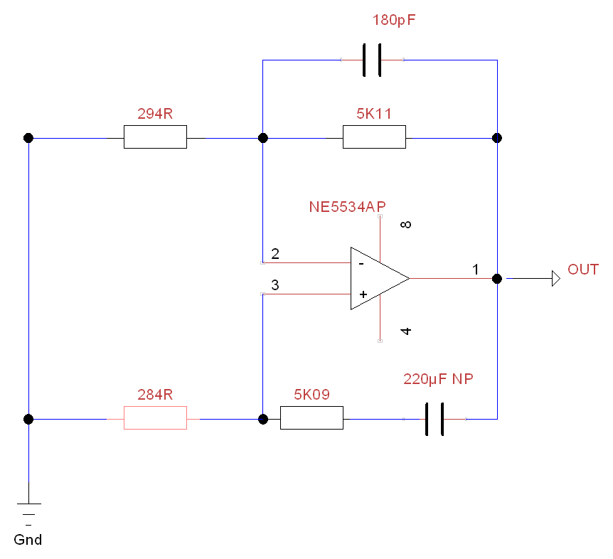
Input coil (2-4) =243.3Ω
Output coil (6-7) =294.6Ω
Output coil (8-10) =284.8Ω
Output coil (9-8) =146.1Ω
Output coil (9-10) =138.7Ω
Circuit resistors
R (linked to 6) =5.11KΩ
R (linked to 10) =5.09KΩ
That's BS, we don't know which channel is which, we don't know the vertical sensitivity of either channel, we don't know the time base. Are the probes 1:1 or 10:1? Etc.
It's just a content-free picture the way it is presented.
Jan

180Hz sine signal
1:1 probes
Time base : forgotten
vertical sensitivity : forgotten (But the same for the two channels)
Before PSU switch
The large sine is the input coil (6-7)
The small sine is the Circuit output.
After PSU switch
The small sine is the input coil (6-7)
The large sine is the Circuit output.
Last edited:
It looks like you have a differential amplifier circuit like in the image attached below.
In the transformer circuit the secondary winding resistances form Ri, and Ro would be the 5.1k resistors. The voltage across the normal (pins 6-7) secondary winding could be represented by a voltage source in series with it's Ri resistance. The other winding of the transformer (pins 8-10) that acts as a resistor could be represented as two voltages sources in series that are equal and opposite in series with it's Ri resistance. Since those two voltages sources cancel out, we can omit them from our model and replace them with a short.
Therefore, what you have is a differential amplifier with a voltage source connected to one Ri and the other Ri connected to ground.
Attachments
Last edited:
It looks like you have a differential amplifier circuit like in the image attached below.
In the transformer circuit the secondary winding resistances form Ri, and Ro would be the 5.1k resistors. The voltage across the normal (pins 6-7) secondary winding could be represented by a voltage source in series with it's Ri resistance. The other winding of the transformer (pins 8-10) that acts as a resistor could be represented as two voltages sources in series that are equal and opposite in series with it's Ri resistance. Since those two voltages sources cancel out, we can omit them from our model and replace them with a short.
Therefore, what you have is a differential amplifier with a voltage source connected to one Ri and the other Ri connected to ground.
If you ignore the transformer :

But since the comportement of the transformer is affected by the circuit this theoretical simplified view of the whole circuit comportement is completely wrong.
No, not at all. If you are concerned about current flowing out of the op-amp into the transformer, it doesn't do anything. The current flows into a winding that is in effect a non-inductive resistor. The fields cancel and no flux is produced, at least as a first-order effect.
Again, one winding (pins 8-10) is wound so it acts like a resistor, not a transformer winding. Half of it is wound clockwise and the other half is wound counterclockwise, so the fields cancel. There is neither input into the op-amp from that transformer winding, nor effective core flux created by op-amp output current flowing into that winding. The winding is only a resistor, that's all, there is no transformer action for that winding.
All the other transformer windings are wound normally, so coupled flux is produced resulting in transformer action.
Why don't you check and see? I think the model I described should come pretty close to predicting the gain you have.
EDIT: You left one thing out of the diagram you produced above. There is no generator representing the normal transformer winding (pins 6-7) secondary EMF which should appear in series with the Ri connected to the op-amp inverting input. Or you could show that as an ideal transformer connected there. Either way amounts to serving the same purpose as far as modeling op-amp circuit.
Last edited:
Also, from the resistance values you measured, it looks like the two windings that form the resistor element are slightly unbalanced. That may very well account for a some small-ish net flux associated with the resistance winding. That could be used to compensate for transformer distortion to some extent, but the effect is probably small enough that it doesn't have much effect on a first order model of what the expected circuit gain would be.
No, not at all. If you are concerned about current flowing out of the op-amp into the transformer, it doesn't do anything. The current flows into a winding that is in effect a non-inductive resistor. The fields cancel and no flux is produced, at least as a first-order effect.
Again, one winding (pins 8-10) is wound so it acts like a resistor, not a transformer winding. Half of it is wound clockwise and the other half is wound counterclockwise, so the fields cancel. There is neither input into the op-amp from that transformer winding, nor effective core flux created by op-amp output current flowing into that winding. The winding is only a resistor, that's all, there is no transformer action for that winding.
All the other transformer windings are wound normally, so coupled flux is produced resulting in transformer action.
Why don't you check and see? I think the model I described should come pretty close to predicting the gain you have.
EDIT: You left one thing out of the diagram you produced above. There is no generator representing the normal transformer winding (pins 6-7) secondary EMF which should appear in series with the Ri connected to the op-amp inverting input. Or you could show that as an ideal transformer connected there. Either way amounts to serving the same purpose as far as modeling op-amp circuit.
Sorry, i'm a lazy guy... there is so much things to represent in the transformer (equivalent circuit model).
To be simple, if the secondary coil (8-10) has no interaction with the core flux, could you explain me how the center tap (9) of this bobin (8-9) is returning half of the signal ?
Also, from the resistance values you measured, it looks like the two windings that form the resistor element are slightly unbalanced. That may very well account for a some small-ish net flux associated with the resistance winding. That could be used to compensate for transformer distortion to some extent, but the effect is probably small enough that it doesn't have much effect on a first order model of what the expected circuit gain would be.
If i balance the two secondaries resistances, the circuit is running into instability.
Sorry, i'm a lazy guy... there is so much things to represent in the transformer (equivalent circuit model).
To be simple, if the secondary coil (8-10) has no interaction with the core flux, could you explain me how the center tap (9) of this bobin (8-9) is returning half of the signal ?
Measuring across 8-9 or accross 9-10 does interact with core flux, as there is no cancellation when they are used alone. They only cancel out when connected in series, due the the inverse phase relationship between them (EDIT: in other words, relative to pin 9, pin 8 and 10 are both in phase with each other, so there is no voltage difference between them).
You may be interested in an old patent that isn't quite what you have here, but is the closest I can find: Patent US5369355 - Compensation circuit for transformer linearization - Google Patents
Both it and what you have are intended to compensate for mostly LF harmonic distortion by using a third winding. With the transformer you have, there may be a little intentional imbalance between the two windings at 8-9 and 9-10 that in sum interacts with core flux (incomplete cancellation of the two fields). In that case, 8-10 would mostly act like a resistor with a little coil added to it to provide a little distortion compensation capability.
Having talked though all of the above, the circuit origin remains rather obscure. In addition, without knowing more about the exact internal transformer design, a more complete and detailed analysis is probably going to be difficult or impossible.
It may be enough to know that this type of circuit seems to be rarely used. Usually if low distortion is desired, a better quality and perhaps physically larger transformer may be preferable over using active compensation.
I suppose if you really wanted to know more about it you could contact the transformer manufacturer and see if they have an applications engineer that can give you some background on it.
Last edited:
This circuit is so called zero field transformer input circuit.
Patent US4567443 - Low-distortion audio amplifier circuit arrangement - Google Patents
Lundahl also make transformers for this application.
pin6 is inverting input and pin7 is gnd. The voltage is equal to noninverting input by virtual short, you know.
The pin6-7 voltage is not input voltage of the whole circuit block.The gain of the circuit is (output - outputgnd)/(input+ - input-) .
Measuring across 8-9 or accross 9-10 does interact with core flux, as there is no cancellation when they are used alone. They only cancel out when connected in series, due the the inverse phase relationship between them (EDIT: in other words, relative to pin 9, pin 8 and 10 are both in phase with each other, so there is no voltage difference between them).
You may be interested in an old patent that isn't quite what you have here, but is the closest I can find: Patent US5369355 - Compensation circuit for transformer linearization - Google Patents
Both it and what you have are intended to compensate for mostly LF harmonic distortion by using a third winding. With the transformer you have, there may be a little intentional imbalance between the two windings at 8-9 and 9-10 that in sum interacts with core flux (incomplete cancellation of the two fields). In that case, 8-10 would mostly act like a resistor with a little coil added to it to provide a little distortion compensation capability.
Having talked though all of the above, the circuit origin remains rather obscure. In addition, without knowing more about the exact internal transformer design, a more complete and detailed analysis is probably going to be difficult or impossible.
It may be enough to know that this type of circuit seems to be rarely used. Usually if low distortion is desired, a better quality and perhaps physically larger transformer may be preferable over using active compensation.
I suppose if you really wanted to know more about it you could contact the transformer manufacturer and see if they have an applications engineer that can give you some background on it.
This circuit is so called zero field transformer input circuit.
Patent US4567443 - Low-distortion audio amplifier circuit arrangement - Google Patents
Lundahl also make transformers for this application.
pin6 is inverting input and pin7 is gnd. The voltage is equal to noninverting input by virtual short, you know.
The pin6-7 voltage is not input voltage of the whole circuit block.The gain of the circuit is (output - outputgnd)/(input+ - input-) .
Thanks for the informations, you are not paid for, so you have my esteem and consideration.
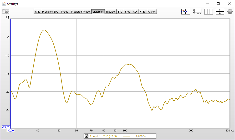
Here is my last THD measurements of The OEP transformer circuit, i have two rebel spikes of THD, one at 0.037% and one at 0.012%.
Have you an idea of how to get rid of them ?
Is this due to my prototype board crappy wiring ?
Without them the THD is about 0.006% at 30Hz.

You might try the application circuit attached below that includes a LF THD trim pot to see if you can null out a little more distortion.
If you over-compensate the THD null adjustment it could be possible for the circuit to oscillate, so just be aware of that possibility.
If you over-compensate the THD null adjustment it could be possible for the circuit to oscillate, so just be aware of that possibility.
Attachments
Last edited:
- Status
- Not open for further replies.
- Home
- Source & Line
- Analog Line Level
- Phase margin fail !
