Hello:
I have a complete tri-amp stereo system I built mostly from ESP boards. In general I am very happy with it. The issue I have been trying to clear up is a fairly loud "pop" heard through the speakers when any one of several fans is turned on and off. I isolated the sound to the preamp and crossover (both make the sound independent of each other, the power amps not affected by themselves) and figured converting them to battery power would solve the problem and be fun and interesting. While the battery power certainly was a success in some ways it do not help with the "pop" from the arcing switches which was a surprise to me. This leads me to believe it must be local RF interference.
The Preamp is based on ESP P06 phono preamp and ESP P88 preamp board. The Crossover is a 3-way active based on 2 P09 boards. These are all op amp based circuits with floating grounds and now powered with a +/- 12 volt battery supply. Out side of the "pop" they are dead quiet.
The preamp makes sense to me as when hooked up directly (by pass the crossover) there is a "pop" in phono mode only.... I assume RF interference picked up by the rather poor stock interconnects from the turntable and the cartridge and high gain. My other interconnects are good quality DIY interconnects so I will upgrade the phono interconnects and see.
What really has me stumped is the crossover. There are about 7 op amps in it but they are mostly running at unity gain in the filters (there are adjustable op amp output stages to balance the levels but these a quite low gain/ no gain). It is assembled in a metal box is battery powered (+/- 12 volts) and besides the "pops" is dead quiet. It makes the same pop whether the inputs are shorted, open, or connected to the preamp (turned off).
My two related questions are what specifically should I look into on the crossover to reduce / eliminate the RF pop and what generally is best practice for DIY assembly to reduce / eliminate local RF interference.
Thank you for any help or advice.
what specifically should I look into on the crossover to reduce / eliminate the RF pop and
what generally is best practice for DIY assembly to reduce / eliminate local RF interference.
I would try first to eliminate the problem at the source by adding an X capacitor
across the fan's switch contacts.
I would try first to eliminate the problem at the source by adding an X capacitor
across the fan's switch contacts.
Thank you... I do have some "X" caps and that is probably easiest way...will try and let you know... still curious trying to understand the how and why an arcing switch affects my battery powered equipment 20 feet away
When the switch arcs it spews a bunch of RF into the air around it, when it gets to your pre-amp it is being detected. The signal wiring and interconnects can be a good antenna.
You haven't said what sort of box the boards are installed in. Metal is preferable for the electro-static shielding it affords to the internal circuitry.
Also sometimes a 0.01uF ceramic cap from RCA grounds (not signal!) to chassis can help, by providing a low impedance path for RFI from the shield to chassis ground.
trying to understand the how and why an arcing switch affects my
battery powered equipment 20 feet away
Post some photos of the chassis internals.
When the switch arcs it spews a bunch of RF into the air around it, when it gets to your pre-amp it is being detected. The signal wiring and interconnects can be a good antenna.
You haven't said what sort of box the boards are installed in. Metal is preferable for the electro-static shielding it affords to the internal circuitry.
Also sometimes a 0.01uF ceramic cap from RCA grounds (not signal!) to chassis can help, by providing a low impedance path for RFI from the shield to chassis ground.
It is a metal box but everything inside is floating with no chassis ground. I did try grounding the metal box to AC ground but it made no difference
Post some photos of the chassis internals.
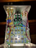
Here is a picture of the crossover.... PS in center back disconnected and now running battery. The "pop" sound is the same on AC or battery.....
Attachments
A floating box can sometimes be worse than no box.levimax said:It is a metal box but everything inside is floating with no chassis ground.
Sometimes it helps, sometimes it doesn't.I did try grounding the metal box to AC ground but it made no difference
Unscreened signal wires are asking for RF trouble. Replace with screened, or at least twisted.Here is a picture of the crossover..
Unscreened signal wires are asking for RF trouble. Replace with screened, or at least twisted.[/QUOTE]
Thanks, I was thinking the same thing after looking at the picture. This was the first project I built and I figured since the AC transformer was far away on the wall and everything was inside a metal box and the signals were fairly high level (after the preamp) that I didn't need shielded wire. Worked out for AC hum but apparently not for RF.
Thanks, I was thinking the same thing after looking at the picture. This was the first project I built and I figured since the AC transformer was far away on the wall and everything was inside a metal box and the signals were fairly high level (after the preamp) that I didn't need shielded wire. Worked out for AC hum but apparently not for RF.
now running battery. The "pop" sound is the same on AC or battery.....
Is there any connection from the audio pcb ground to the chassis, either direct
or through a resistor?
Is there any connection from the audio pcb ground to the chassis, either direct
or through a resistor?
No everything is "floating" and insulated from the metal case. When on AC a Wal-Wart supplies AC to regulated PS when on battery direct connection to +/- 12 volt DC. I did try grounding case to AC mains ground which made no difference.
I would try first to eliminate the problem at the source by adding an X capacitor
across the fan's switch contacts.
Thank you rayma and everyone for your suggestions. A 0.1uf "X" capacitor across the fan switch eliminated the issue. I also now see I need to use shielded wire even if inside a metal case on all signal wires.
I also now see I need to use shielded wire even if inside a metal case on all signal wires.
The metal chassis should not be floating. For safety it must be connected to the safety ground
(green wire in the power cord) of the AC line.
Try connecting a 10R resistor from the audio pcb common to the chassis.
If that helps with noise, you can permanently install the usual network (a diode block,
capacitor, and resistor, all in parallel), between the chassis and the audio common.
Last edited:
The metal chassis should not be floating. For safety it must be connected to the safety ground
(green wire in the power cord) of the AC line.
For AC I use a 16 volt 1 amp "Wall Transformer" and then a PS board inside the case. My understanding is that this is safe and tends to reduce ground loop issue. It may not be the best at RF shielding though.
For AC I use a 16 volt 1 amp "Wall Transformer" and then a PS board inside the case.
My understanding is that this is safe and tends to reduce ground loop issue.
It may not be the best at RF shielding though.
This relies on the wall wart isolation for safety and may be ok. Still, if the chassis is floating,
it only serves to couple noise to the circuitry, rather than to shield it. Shielding the wires
may not help much, depending on the details.
Last edited:
The case MUST be conected to reference point of the PCB's, directly or through a nerwork similary to what is described in post 13.
Q: way you use relay an not directly one powerful transistor to power the fans? You use an AC fans?
Put a PI filter on the fan wires. 2 x 10nF and a 10-100µH series. Shield or at least twist the wires between fan and filter. Put a X cap directly across fan connection as near to fan as posiblle.
Q: way you use relay an not directly one powerful transistor to power the fans? You use an AC fans?
Put a PI filter on the fan wires. 2 x 10nF and a 10-100µH series. Shield or at least twist the wires between fan and filter. Put a X cap directly across fan connection as near to fan as posiblle.
Last edited:
Q: way you use relay an not directly one powerful transistor to power the fans? You use an AC fans?
The fan I was referring to was a "bathroom fan" which make a loud "pop" in the speakers when turned on and off caused by mains AC arcing in the switch creating RF.
I understand now.
What type of interconnect do you use?
Are shielded?
Interconnects are shielded (Belden 1505f cable). Even if I use shorting plugs on input it still picks up "pop" so must be RF.
Interconnects are shielded (Belden 1505f cable). Even if I use shorting plugs on input it still picks up "pop" so must be RF.
this tells you you have two problems.
a.) an emi emitter that needs attention at the source end. (done - your X cap addition).
b.) the amp/receiver is susceptible to interference.
You should be looking to solve BOTH problems.
Add interference attenuation filters to your amp/receiver. Preferably to EVERY cable that enters the metal enclosure.
Add bandwidth limiting filtering to the INPUT of each analogue stage.
- Status
- This old topic is closed. If you want to reopen this topic, contact a moderator using the "Report Post" button.
- Home
- Source & Line
- Analog Line Level
- Apparent RF Issues Pre-amp and Crossover