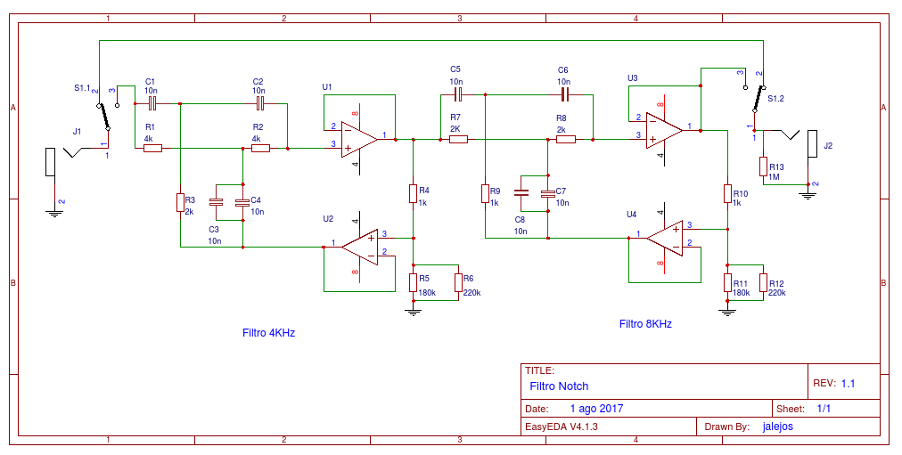
I need to eliminate two frequencies of 4KHz and 8KHz that get me through the guitar pickup (aerial interference). I have done the assembly of the attached diagram, but I only get a reduction of about 3dB on the calculated frequency (4KHz and 8KHz).
Are the filters well connected in series? Would it be better to connect them in parallel with an adder on the output?
Thank you.
Are the filters well connected in series? Would it be better to connect them in parallel with an adder on the output?
Thank you.
I only get a reduction of about 3dB on the calculated frequency (4KHz and 8KHz).
There should be a unity gain input buffer before the first filter. Having the filters in series is fine.
It looks like the ratio of (R5//R6)/R4 is too high, try more like a ratio of 10.
Make a similar change for the second stage. Are you using precision, matched R and C?
Last edited:
Having seen that -40dB voltage divider is made exactly from 1k 180k||220k) I thought I would look for the resistor combination that gives an exact -20dB voltage divider.
We need 1k & 9k for that 1/10th ratio.
12k and 36k in parallel give 9k and there we have it:
1k12k||36k) for -20dB.
1k180k||220k) for -40dB.
180k||220k) I thought I would look for the resistor combination that gives an exact -20dB voltage divider.We need 1k & 9k for that 1/10th ratio.
12k and 36k in parallel give 9k and there we have it:
1k
12k||36k) for -20dB.1k
180k||220k) for -40dB.Thanks for the answers. As it is a guitar pickup, my intention is that it attenuate the maximum of these two frequencies and that the bandwidth is the minimum, so as not to cut adjacent frequencies.
The resistances are 0.1% of metallic film, and the polyester capacitors are 5% tolerance.
The calculations of the values I have taken from here:
Active Twin - T - Notch Filter Calculator
The resistances are 0.1% of metallic film, and the polyester capacitors are 5% tolerance.
The calculations of the values I have taken from here:
Active Twin - T - Notch Filter Calculator
Using 0.1% for resistors and 5% for capacitors seems wrong.
Surely you want/need similar tolerances for both Resistors and Capacitors. Especially for tuning in a deep notch.
remove your caps and measure them to at least two significant figures, or three sigfig if you have a good enough instrument.
find your highest and lowest. select one highest and one lowest and place them as C3 & C4
select the next highest and next lowest and place them as C7 & C8
you now have 4 left.
Take the lower pair and they become C1 & C2, take the upper pair and they become C5 & C6
You now have much better selection of values that probably get you to better than 1% from 5% caps.
If it turns out that your caps are much closer than +-5% then you end up with that measured selection method with far better than +-1%.
If the resulting notch frequency is not quite on target, then you can trim the resistor values to bring the actual onto to target frequencies.
Last edited:
Yes, that circuit needs fairly good component matching to get a deep notch. The bootstrap part of the circuit does not deepen the notch but narrows it. However, I would expect better than -3dB even with 5% mismatch.
These filters must be connected in series, as you have them. Connecting in parallel will not work.
These filters must be connected in series, as you have them. Connecting in parallel will not work.
There should be a unity gain input buffer before the first filter. Having the filters in series is fine.
It looks like the ratio of (R5//R6)/R4 is too high, try more like a ratio of 10.
Make a similar change for the second stage. Are you using precision, matched R and C?
Buffer added and reduced the ratio R5 // R6 R4. Now better.
remove your caps and measure them to at least two significant figures, or three sigfig if you have a good enough instrument.
find your highest and lowest. select one highest and one lowest and place them as C3 & C4
select the next highest and next lowest and place them as C7 & C8
you now have 4 left.
Take the lower pair and they become C1 & C2, take the upper pair and they become C5 & C6
You now have much better selection of values that probably get you to better than 1% from 5% caps.
If it turns out that your caps are much closer than +-5% then you end up with that measured selection method with far better than +-1%.
If the resulting notch frequency is not quite on target, then you can trim the resistor values to bring the actual onto to target frequencies.
Done.
Now, with Q being somewhat larger, the bandwidth is also larger and cuts adjacent frequencies. I will put an adjustable resistance to try to find the optimum point by adjusting the Q.
Following your advice, I have made some modifications. I have added two buffers in each of the inputs. I added an adjustable resistance of 10K (in the scheme mark 100K but it is wrong) to make a fine adjustment of the Q. I have replaced the capacitors by Wima models of 2% of tolerance and I have also matched them. The frequencies are now at 3.85KHz and 7.8KHz. The adjustment of Q is very critical. You might want to add a series adjustable resistor with R3-R7 for fine tuning.
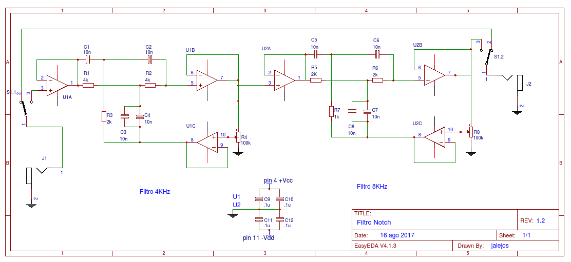
I have added two buffers in each of the inputs.
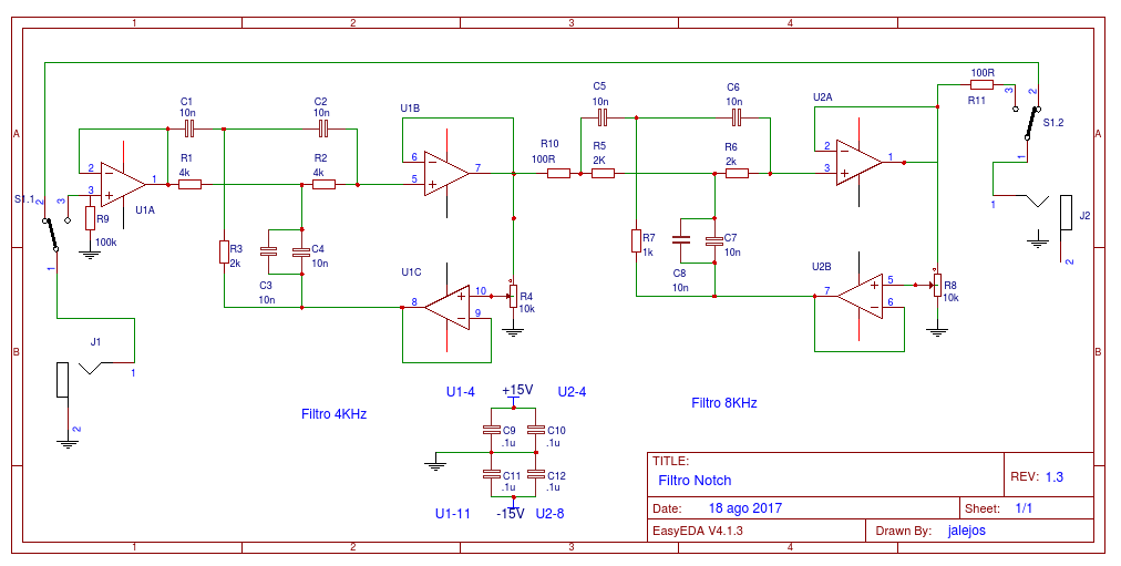
I'd also add input resistors to ground (before the buffers) of your choice 10k-100k.
The second buffer U2A is not really necessary, since op amp U1B provides that function.
Last edited:
The input resistors, also in U1B and U2B?
For each U1A, from the positive input (pin 3) to ground.
Remember that op amp U2A is not necessary to use in the circuit at all.
Last edited:
I need to eliminate two frequencies of 4KHz and 8KHz that get me through the guitar pickup (aerial interference). I have done the assembly of the attached diagram, but I only get a reduction of about 3dB on the calculated frequency (4KHz and 8KHz).
I'm just curious where you are getting the 4kHz and 8kHz interference. I have no problem with the idea of designing a notch filter but what about eliminating or reducing the source and demodulator of this interference?
The recording studio is next to a workshop with CNC machines. I found out that one of the CNC machines, when it starts up, generates such interference at 4KHz and 8KHz (I suppose it will be the motor or the movement of the axes). These interferences are picked up by the guitar pickups and recorded.
That's unfortunate. The PWM frequency of servo and spindle drives of CNC machines do operate in the 3-4kHz region. I used to do work on those powerful inverters and have always wondered how much RF interference they can cause.
It is imperative to prevent AM demodulation of the RFI at the earliest high gain stage (your preamp) or else it will end up in the audible range. Once it gets demodulated, you will have great difficulty getting rid of it. Some form of RF decoupling and filtering should be implemented to prevent diode junctions inside transistors and op-amps from rectifying the unwanted RF energy.
I'm curious of the type of guitar pickup you are using, the length and type of cabling going into the preamp and the preamp model itself. Using batteries will help isolate any of the line conducted RFI.
That's unfortunate. The PWM frequency of servo and spindle drives of CNC machines do operate in the 3-4kHz region. I used to do work on those powerful inverters and have always wondered how much RF interference they can cause.
It is imperative to prevent AM demodulation of the RFI at the earliest high gain stage (your preamp) or else it will end up in the audible range. Once it gets demodulated, you will have great difficulty getting rid of it. Some form of RF decoupling and filtering should be implemented to prevent diode junctions inside transistors and op-amps from rectifying the unwanted RF energy.
I'm curious of the type of guitar pickup you are using, the length and type of cabling going into the preamp and the preamp model itself. Using batteries will help isolate any of the line conducted RFI.
Being a recording studio, neither the guitar pickups nor the amplis to use are fixed, depends totally on each case, each musical group and each recording, the same with the cables and recording system, can be a Amplifier of microphone or the line of a guitar, a head of more or less power, a double or simple pickup, etc.
This circuit would be connected between the pickup of the guitar and the first preamplifier.
- Status
- This old topic is closed. If you want to reopen this topic, contact a moderator using the "Report Post" button.
- Home
- Source & Line
- Analog Line Level
- Dual Notch filter 4KHz and 8KHz