Thought the attached schematic might help some readers.
It's an NE5532 Buffer listed on Ebay by umpteen sellers.
NE5532 OP-AMP HIFI Audio Preamplifier Dual Preamp Board for Bluetooth Pre-amp K9 | eBay
Take care when selecting buffers - this is split supply, some others are single supply.
It's an NE5532 Buffer listed on Ebay by umpteen sellers.
NE5532 OP-AMP HIFI Audio Preamplifier Dual Preamp Board for Bluetooth Pre-amp K9 | eBay
Take care when selecting buffers - this is split supply, some others are single supply.
Attachments
I should have stated, one half shown.
Complete circuit is dual.
Now I've posted the schematic I have a number of questions.
1 - The buffer is inverting. What is the purpose of the 100K to ground? Textbook examples do not show this.
2 - gain - 100/10 = 10 or does the 100K to ground change this?
3 - Why the two 100R resistors in the supply lines?
4 - the purpose of the 2 small caps across the feedback resistors?
I bought a pair, not realising they were inverting.
Can I still use as a differential buffer, using one half for Hot & one half for Cold signal?
Attached is the recommended input buffer I was aiming for.
Attachments
1) stops he output flapping around if the i/p is disconnected and keeps Zin reasonable; not infinite.
2) gain cannot be >1 in this configuration. It is 1% less than unity.
100K / (100+1)K
3) these help the decoupling effect of the psu caps.
4) often required to keep things stable: eliminate output peak on square-wave and/or stop oscillation.
2) gain cannot be >1 in this configuration. It is 1% less than unity.
100K / (100+1)K
3) these help the decoupling effect of the psu caps.
4) often required to keep things stable: eliminate output peak on square-wave and/or stop oscillation.
The 100k is odd in an application like this. It increases something called 'noise gain' and is inappropriate here, although there are instances when it can be used. Just not here ")
It does not materially effect the closed loop gain (as configured here).
The 100 ohms increase the effectiveness of the rail decoupling caps. 100 ohm is perhaps a little high though.
The caps tame the high frequencies and aids stability. It is called 'phase lead compensation' and increases the amplifiers phase margins.
Your second circuit is fine, and that needs the 100k to provide a DC reference point (which is ground) to correctly bias the input.
I bought a pair, not realising they were inverting.
Just to add... that to correct the phase inversion of the first circuit (the pdf one) you need to add a second inverting stage, not a buffer such as your attached drawing. If that is what you are trying to do.
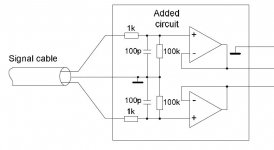
the post2 sch can be improved by connecting the two filtering capacitors direct to chassis rather than to audio ground.
The 100k stay connected to audio ground.
If you can fit the 100r direct to the connector pins and then from the 100r via the caps to chassis then you have the least internal cabling with the interference spraying emi inside the enclosure.
Depending on the shape of the connector pins and the housing you may be able to use smd resistor+smd cap without any wiring to maximise the filtering effect by omitting the inductance of the leads.
You are showing a connection from the screen coming in past the enclosure panel to a BAR symbol. then to the junctions of the caps and 100k.
Is this connection from a balanced impedance cable screen/shield?
Last edited:
Can you explain this?..............
2) gain cannot be >1 in this configuration. It is 1% less than unity.
100K / (100+1)K............
Thanks for all the responses.
The circuit post #2 is from the amplifier data sheet - Anaview AMS0100.
http://www.anaview.com/sites/default/files/PDS AMS0100-K.pdf
Page 33.
I am feeding the amp with 4mtr long balanced cable - DRV134 in my pre-amp.
Amp is connected BTL. Input impedance is ~1.2K.
I purchased the Ebay board hoping to use (both halves) as a balanced input buffer.
Can I use it or does the inverting configuration make it unsuitable?
If unsuitable, I'll build the recommended circuit on stripboard.
The fact that it inverts is no disadvantage to the operation. Absolute phase is something that is argued about... if it bothers you then all you need do is reverse your speaker connections to correct it.
The ebay board is drawn as an amplifier of -10 gain (- denotes inverting). To make an inverting buffer (-1 gain) you need to replace the 100k feedback with a 10k. The extra 100k shown can be left in place.
The input impedance of the inverting circuit is equal to the first 10k alone. If that is to low then make both the input and feedback the same value and increase them to say 22k.
The small cap across the 100k will have its effect altered by changing the 100k to 10k but that is probably a non problem. Out of interest, what value is the cap ?
You should also add a small resistor to the output of the opamp of around 33 ohms or 47 ohms. That eliminates capacitive loading effects from causing stability issues.
If the opamp is an NE5532 then there will be a small DC offset at the buffer output which means that you may need to think of adding a small cap at the output of the opamp to block it.
Can you explain this?
Its simple, Andrew! I was looking at the wrong schematic!
Thanks Mooly.
I will obtain a few 22K SMD resistors and get modding (2 boards).
I'll measure the cap (unmarked) when I mod.
I am connecting direct to power amp <10cm cable, do I really need output resistors?
I will measure for DC offset at the output. If both channels measure the same DC they will cancel in a balanced set up so can be disregarded?
The output resistor is a good general safeguard, however 10cm cable run should be fine.
The offset problem comes not just from any possible DC applied from the source but also internally generated DC offset within the 5532, caused by the fact it is a bjt type opamp and so has 'significant' bias currents flowing out of the two inputs. Those tiny currents develop a voltage across the source impedance which then appear as a DC voltage at the amplifier inputs... ready to be amplified by whatever gain you have the opamp running at.
The offset problem comes not just from any possible DC applied from the source but also internally generated DC offset within the 5532, caused by the fact it is a bjt type opamp and so has 'significant' bias currents flowing out of the two inputs. Those tiny currents develop a voltage across the source impedance which then appear as a DC voltage at the amplifier inputs... ready to be amplified by whatever gain you have the opamp running at.
That's OK.Its simple, Andrew! I was looking at the wrong schematic!
I built a compact 5532 buffer on a small Radio Shack proto board. It's just a straight non-inverting unity gain buffer with capacitor coupled inputs, resistor isolated bypass caps, and basic diode protection. It is DC optimized (one more resistor per channel) and has an output offset voltage of 0.00 mV on one channel, and 0.90 mV on the other channel. That's with a 5532.
It's totally conventional and super easy. It's made of 100% leftover parts (maybe $20 worth). I use it for prototyping and testing. It works great and it sounds great!
It's totally conventional and super easy. It's made of 100% leftover parts (maybe $20 worth). I use it for prototyping and testing. It works great and it sounds great!
I built a compact 5532 buffer on a small Radio Shack proto board. It's just a straight non-inverting unity gain buffer with capacitor coupled inputs, resistor isolated bypass caps, and basic diode protection. It is DC optimized (one more resistor per channel) and has an output offset voltage of 0.00 mV on one channel, and 0.90 mV on the other channel. That's with a 5532.
It's totally conventional and super easy. It's made of 100% leftover parts (maybe $20 worth). I use it for prototyping and testing. It works great and it sounds great!
Sounds awesome! I love making stuff from leftovers as well as eating leftovers.
Since it's "conventional and super easy", how about posting a schematic so we can see for ourselves?
DC optimized? Hmmm...do you mean DC coupled outputs, or placing electrolytic caps in series with the resistors from the inverting inputs to ground, or both?
After all, we have to some place for that nasty DC to go with those good 'ole sounding bipolar op-amps.
Also, I don't think I've seen this basic diode protection on op-amp circuits before. So posting a schematic will show me and others here what that is all about.
Keep up the good work Fast Eddie and thanks for sharing!
DC optimised simply means equalising the input offset voltages to minimise output offset i.e. you add a resistor equal in value to the feedback resistor in series with the non inverting input. The downside of that is that the node then becomes sensitive to AC pickup, and so if needed can be decoupled with a cap.
DC optimised simply means equalising the input offset voltages to minimise output offset i.e. you add a resistor equal in value to the feedback resistor in series with the non inverting input. The downside of that is that the node then becomes sensitive to AC pickup, and so if needed can be decoupled with a cap.
Absolutely correct. Worth doing if you don't have to juggle other values in the circuit to make it work. With a capacitor coupled input buffer it's just one extra resistor per channel, no other changes.
Some audio circuits (like some tone controls and volume controls) can never be DC optimized without adding extra electrolytic capacitors into the signal chain. It's not worth it. However, using a higher input impedance op amp (like the OPA2134) reduces the offset voltages in these circuits. But don't forget that the noise characteristics of the 5532 and 2134 are completely different; haphazard substitution of a 2134 for a 5532 can degrade noise performance. Cliff notes 2134 has low current input noise, and 5532 has low voltage input noise. Translation 2134 is better with higher resistances and impedances; 5532 is better with lower resistances and impedances. (Also, the disadvantage of the relatively low non-inverting input impedance of the 5532 is virtually eliminated in inverting circuits.)
Last edited:
DC optimised simply means equalising the input offset voltages to minimise output offset i.e. you add a resistor equal in value to the feedback resistor in series with the non inverting input. The downside of that is that the node then becomes sensitive to AC pickup, and so if needed can be decoupled with a cap.
Thanks Mooly.
@Fast Eddie, I asked you about the "diode protection" above.
Can you post a photo of this and explain how it works?
Thanks Mooly.
@Fast Eddie, I asked you about the "diode protection" above.
Can you post a photo of this and explain how it works?
Yes, I did not forget your question.
My only digital camera is broken and besides I'm too blind to use it any more. I will have to enlist help. But I do intend to write a few wiki articles, complete with pictures and schematics, hopefully soon. They will hopefully show practical techniques to design and build various audio circuits using "at-home" technology.
The protection diodes are simply reverse biased diodes from the rails to the inputs and outputs of your circuit. That's it. I place these wherever there is a coupling capacitor in the input or output circuit. I also use them on the feedback electrolytic capacitor. In normal operation they are reverse biased and do nothing; so they do not introduce noise from the rails or any other negative effects. But when you power down, the diodes will force the audio capacitors to collapse with the rails - preventing potential latch up or damage (worse case), and minimizing thumps. Since I tend to use larger value coupling capacitors I got into this habit.
For line level circuits the 1N914 will do. You can buy 100 for around $5 at Digikey.
- Status
- This old topic is closed. If you want to reopen this topic, contact a moderator using the "Report Post" button.
- Home
- Source & Line
- Analog Line Level
- NE5532 Buffer