Gary that post18 common emitter stage has a high output impedance.
It really needs a Buffer to lower the output impedance. The Buffer needs to have sufficient current capability to drive any cables attached to the output.
The post20 sch is a common collector (emitter follower) and has a low output impedance.
If the output is set to ~4Vdc then R19 passes ~1mA.
that gives your output current capability ~ +-0.9mApk
That seems a bit low to drive a cable. Opamps usually have +-20mApk
Last edited:
Yes, I see, about post 18 it has higher output impedance, but still a nice input interface with good input impedance, and as you said you can just add 1 more transistor and 1 resistor and you've got low impedance.
Post20 is an emitter follower, but I liked the idea of having no lower biasing resistor and just using the resistance across the emitter (hfe*Re) to bias the input/output. I know hfe can be variable, but guitar signal is small enough and the hfe would have to be way off to have the input or output clip. I thought the main advantage of leaving off the lower bias resistor is that you don't have to parallel 3 resistances (2 biasing resistors and he x Re) when calculating input impedance, only 2 resistances. Plus that lets you use a little lower emitter resistor which I think puts the transistor in an operating region where hfe is higher, at least for the 2n3904 datasheet I looked at.
I do see the point about output current capability. I was thinking if input and output impedance matching was correct, the current wouldn't be an issue.
If I'm understanding what your saying, your meaning the op amp can produce more current into the load than the transistor can. If I've got this right isn't this the same thing as saying that the load impedance can be lower for the op amp? This makes sense the op amp has much lower output impedance. In other words, I'm thinking in terms of voltage loss and impedance matching. As long as the output impedance of the buffer is less than 10xs than the load, I was thinking it would work ok.
I see what your saying. In general you must plan for output current capability separately. But in planning, the output current needed would depend on the load. I think in this circuit post20, the output impedance is say 100 ohms depending on source. But really could only drive something like 10k because of current capability limitations.
the Rin when resistive is not a difficult load.
10k resistive fed from a CDP or similar digital with ~2.2Vac will demand a maximum peak current of 2.2*sqrt(2)/10k = 0.31mApk
That is an easy loading.
Change to a 1k for Rin and you still have a fairly easy loading of 3.1mApk.
That can be satisfied with a 7mA biased (BL grade 2sk170) single ended output device. A B1, or DCB1, can do that.
The difficult part is driving capacitance.
The cable and RF attenuation built into the Receiver can easily demand more current than a 10k input stage and in worst case conditions could double the current of a 2k input impedance.
Output impedance of less than 1k is often good enough for short and medium length cables. Longer cables would like to see <200ohms. Balanced impedance connections which are designed for long lengths of cable are often fed from source impedances <50ohms AND with high current capability.
> I don't think there is any correlation between output impedance and output current capability.
"Current Gain". In BJT, hFE.
Ignoring practical details like Bias, and assuming Unity Gain, Zin is at most hFE*Rload.
In real life, your hFE=140 part will use-up 20%-50% of its hFE in biasing losses. So Current Gain for AC signals is maybe 50. If Zin must be 500K, load driving ability is no lower than 10K.
Since 1959, the answer has been simple and cheap. Use more transistors. Two of hFE=140 gives potential Current Gain of 20,000, wow! And compound pairs can be thriftier with bias losses. It is easy to get Zin > 500K and load 100 Ohms.
Since 1972, the answer has been even simpler. Buy 7 to 47 fully engineered and specified transistors in one blob, a chip. Even if just 3 stages of current gain, you can get Zin > 1Meg and Zout < 10 Ohms.
Attachments
Thank you PRR
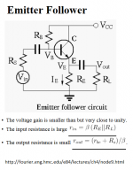
Here is a nice discussion about the emitter follower.
Emitter Follower
It nicely incorporates the emitter resistor and the load the follower is driving. (By the way, some discussions call the emitter resistor the "load" resistor. Not sure what the best convention is but I am referring to the resistor on the emitter as an emitter resistor and the "load" is the load the emitter follower is driving.
If you look at the equations in the attached figure, you can see how input impedance, output impedance and load are related.
For example, r source = 10k hfe=100, load being driven 1k
What basically has caused me problems when I first started examining this circuit is that at first I thought, great, this emitter follower has 100ohm output (for example 10k source, beta 100) , how wonderful, I can drive a 1k load. And as far as I can tell the circuit does have 100ohm output impedance.
However when you try to drive, say 1k load, the load and the emitter resistor get paralleled when calculating the input impedance, and this lowers the input impedance, thereby attenuating the input signal.
Anyhow I think if you design an emitter follower, and your load is 10x's the emitter resistor, this would work ok.
Attachments
> wonderful, I can drive a 1k load
Only for *small* signals.
The low Zout is due to NFB. When the circuit runs out of current, the NFB quits. If your DC emitter resistor is 1K, you can not get full swing in a 1K AC load. You need to load with 2X to 5X the DC resistor, 2K to 5K load.
The low-mid frequency of most loads in audio is 10K and up. But if you are driving long cables, they suck highs. A 30 foot cable is 10,000pFd and gets down toward 1K reactance at the top of the audio band. There's usually less signal up there, so it may be OK.
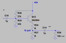
Can you use a potentiometer as an emitter resistor for a volume/level control?
I just wanted to see if anyone had any insight about using a potentiometer as the emitter resistor on an emitter follower for a volume/level control. Is this a good or bad idea and why? Here was my idea and this is just a quick example circuit to show what I was thinking.
I just wanted to see if anyone had any insight about using a potentiometer as the emitter resistor on an emitter follower for a volume/level control. Is this a good or bad idea and why? Here was my idea and this is just a quick example circuit to show what I was thinking.
Attachments
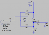
Simple 1Meg input impedance single transistor follower, bootstrapped
PRR, I see what you mean, I hadn't thought about that! Someone could create their own ~4v sine wave under the right conditions. If I would decide to try something like that maybe I would put a pair of 1v or so clipping diodes just to limit this. I was thinking about running something like this into the next stage maybe an amp stage 10k input impedance. So it just seemed like an easy thing to use. At some point I will try it to see how it works.
I have been reading about similar circuits recently and wanted to compliment a few people who have done a great job in their articles. I know a lot of people consider this yesterdays technology, but I really want to learn about older simple circuits and newer ones. And these techniques are still used here and there.
Ray Marston deserves kudos for the Bipolar Transistor Cookbook in the Nuts and Volts magazine. This is a great read explaining the basic and easy practical circuits. Here is the link to part 2 in an 8 part series which talks about emitter followers and more:
BIPOLAR TRANSISTOR COOKBOOK — PART 2 - Nuts & Volts Magazine - For The Electronics Hobbyist
Another great article posted last year is by Rod Elliott and he reviews old follower techniques, and I really appreciated this article:
Voltage Followers
Thank you Ray and Rod.
After reading these articles I put together this circuit in LTspice and when I get home, I thought I would try it out to see what it sounds like. As shown the circuit, has a 33k external load, but I think if you used a 10k load, but smaller signal like .5v or less, it would work ok. It seems to clip around amplitude of 3v roughly. With a 33k external load the input impedance was simulated to be 1.7Meg. With 10k external load the input impedance was simulated to be 1Meg.
Attachments
basic test of boostrapped input buffer
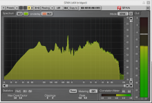
Here is some basic tests I did on the above circuit. I was just trying different simple solutions (other than op-amp) to see if I could get higher input impedance >1Meg. I tried the bootstrap as shown in the schematic (measured 1.7Meg). I just ran some music ("More Than a Feeling" -Boston, again).
The buffer went into a 100k input impedance interface with input level cranked all the way to 10, and music was very low level. I was just trying to accentuate any noise in the circuit. Mainly I wanted to look at the spectrum analysis to make sure it wasn't altering the signal levels over the audio spectrum. There are 2 signals, the straight signal into a channel (yellow) and signal after buffer (green).
They look very similar and you can see the noise floor above 16k or so. (I guess the iPhone must roll off above 16k because as you can see there is no spectral content showing up).
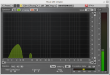
Just out of curiosity, I grounded the input, which would simulate turning a volume pot to zero, and then made a recording of the noise. There is a 60hz signal and another less than 200hz.
Here is some basic tests I did on the above circuit. I was just trying different simple solutions (other than op-amp) to see if I could get higher input impedance >1Meg. I tried the bootstrap as shown in the schematic (measured 1.7Meg). I just ran some music ("More Than a Feeling" -Boston, again).
The buffer went into a 100k input impedance interface with input level cranked all the way to 10, and music was very low level. I was just trying to accentuate any noise in the circuit. Mainly I wanted to look at the spectrum analysis to make sure it wasn't altering the signal levels over the audio spectrum. There are 2 signals, the straight signal into a channel (yellow) and signal after buffer (green).
They look very similar and you can see the noise floor above 16k or so. (I guess the iPhone must roll off above 16k because as you can see there is no spectral content showing up).
Just out of curiosity, I grounded the input, which would simulate turning a volume pot to zero, and then made a recording of the noise. There is a 60hz signal and another less than 200hz.
Attachments

- Status
- This old topic is closed. If you want to reopen this topic, contact a moderator using the "Report Post" button.
- Home
- Source & Line
- Analog Line Level
- Can I use a Darlington Pair for an Input Buffer