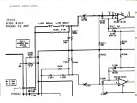
The design choice for R109 surprises me a bit: 2600 ohms.
What were the considerations & calculations which led you to conclude that 2.6K is optimum?
For example, why isn't R109 a duplicate of R108 (3.9K)? Why isn't it zero ohms (a short to negative supply)? Why isn't it (R106 / Beta_Q402) ? What's so great about 2.6K ohms?
_
What were the considerations & calculations which led you to conclude that 2.6K is optimum?
For example, why isn't R109 a duplicate of R108 (3.9K)? Why isn't it zero ohms (a short to negative supply)? Why isn't it (R106 / Beta_Q402) ? What's so great about 2.6K ohms?
_
Attachments
Member
Joined 2009
Paid Member
Good question. It started out as 2k2 copied directly from the NAD3020 and adjusted to 2k6 because I'm using a higher -Ve rail voltage than the NAD. I didn't try to understand the original designer choice but my assumption is that it was designed to match the operating conditions of the two Rush Casode devices.
Member
Joined 2009
Paid Member
There are many things that I don't understand, it's a matter of 'granularity' - some of the circuits I use I have designed in details some re-use building blocks proven elsewhere. The idea with the phono was to re-use the NAD3020. It has evolved since then and no longer matches any existing designs but still closely resembles several posted schematics. It's a good suggestion to step back and realize that this tinkering is tantamount to a new design and worthy of some further thought. At some point the topology will be 'frozen' so I can get the design files out to a fab-house (something has to be built eventually !) but component values don't need to be settled on until I order parts and even then some flexibility.
So, you highlighted the Rush Cascode front-end, the error amplifier that takes the voltage differential between the two bases to modulate the current flow. We have a collector load on the 'top' npn device to generate a voltage signal needed to feed the next stage. The value of this resistor is decided by looking at the dc-voltage required at the next stage for proper bias and then R = V/I where I is the idle current through the Cascode. There is a fair bit of flexibility with this choice but lower currents reduce the base input current so it has some impact on noise. Let's take the value used as a given. The pnp device doesn't need a collector load resistor? If we want the npn and pnp devices to have similar power dissipation, Vce operating points and Miller input capacitance then we have some criteria to choose a resistor. The dc current though the collector load resistors on the pnp and npn devices isn't the same because the next stage adds it's base input current.
So, you highlighted the Rush Cascode front-end, the error amplifier that takes the voltage differential between the two bases to modulate the current flow. We have a collector load on the 'top' npn device to generate a voltage signal needed to feed the next stage. The value of this resistor is decided by looking at the dc-voltage required at the next stage for proper bias and then R = V/I where I is the idle current through the Cascode. There is a fair bit of flexibility with this choice but lower currents reduce the base input current so it has some impact on noise. Let's take the value used as a given. The pnp device doesn't need a collector load resistor? If we want the npn and pnp devices to have similar power dissipation, Vce operating points and Miller input capacitance then we have some criteria to choose a resistor. The dc current though the collector load resistors on the pnp and npn devices isn't the same because the next stage adds it's base input current.
Last edited:
Member
Joined 2009
Paid Member
Board#2 Gain and Tone
With Board#1 more or less settled the next board is the gain stage with tone controls.
There are some tradeoffs I imagine, between including the tone controls within the gain stage feedback loop, or simply having them in-line with the input to the gain stage.
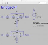
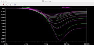
As I have never found the traditional treble-bass set of controls very useful and simplicity being preferred my thought is to devise a single-knob tone control. A tilt control has been suggested but I don't think the usual hi-fi (e.g. Quad style) types will suit either because it's essentially a treble-bass control (for most of those I've seen). What I want is something that focuses on the 'presence' region. And I've noticed that such tone controls exist, have a big tradition behind them - in the guitar world. In most cases they are passive and hence would go in-line before the gain stage.
A bridged-tee-notch filter has some desirable properties in this regard.
With Board#1 more or less settled the next board is the gain stage with tone controls.
There are some tradeoffs I imagine, between including the tone controls within the gain stage feedback loop, or simply having them in-line with the input to the gain stage.
As I have never found the traditional treble-bass set of controls very useful and simplicity being preferred my thought is to devise a single-knob tone control. A tilt control has been suggested but I don't think the usual hi-fi (e.g. Quad style) types will suit either because it's essentially a treble-bass control (for most of those I've seen). What I want is something that focuses on the 'presence' region. And I've noticed that such tone controls exist, have a big tradition behind them - in the guitar world. In most cases they are passive and hence would go in-line before the gain stage.
A bridged-tee-notch filter has some desirable properties in this regard.
Last edited:
It looks to me as if it wouldn't be that hard to fit a digital input to this pre-amp. See attached image, a Pi-zero with DAC on top. May not be expensive but I read at least one review that compared it favourably to some expensive kit of just two years ago.
I have that exact combo and it sounded quite fine to my ears. As good as any digital source, really.
Member
Joined 2009
Paid Member
That's encouraging!I have that exact combo and it sounded quite fine to my ears. As good as any digital source, really.
I would like to make one of these but now I think it will be in a dedicated box. Digital in one box, analogue in the other. Not because I think it'll necessarily sound better to my ears, but digital evolves quickly, I want this pre-amp to last awhile and using somewhat traditional analogue circuits means it'll be a nice 'keeper'.
I simulated a circuit in LTSPice, what I have in post #478 is supposed to be the same but I'l have to check by comparing them. I simulated a lot of variations, I looked at the NAD3020, the NAD3080, the NAIM, the Haffler and some in-between so hopefully I didn't get things wrong.Gareth, have you simulated that phono stage in post #478?
Last edited:
mains powered SMPS are usually housed in a metal enclosure that is protected by a PE connection.
The SMPS output is usually connected to the protected enclosure.
Is this asking about that connection
That is very rare IME. Most OEM switching power supplies are floating output specifically so you can use them as a negative or positive grounded supply. Or in some cases, use two units for a +/- split supply as most multi output SMPS's do not offer symmetrical bi-polar output currents due to the secondary HF AC waveform not being a 50% duty cycle. (hard to do that with PWM)! Many negative outputs are via onboard 3 terminal linear regulator chips and a fraction of the main output current.
Now of course the E or Earth terminal on the primary side is tied to the metal case if so equipped. But if you have an EMI problem, you don't need to use the PE terminal and could float the metal cased SMPS. Just don't try to get that through UL or any other European safety agency if in a commercial product

Last edited:
Member
Joined 2009
Paid Member
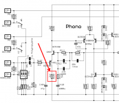
Gareth, have you simulated that phono stage in post #478?
OK, I checked and it's the same. And I see that the now infamous collector load resistor on the input device doesn't do much to equalize the Vce across the two Rush Cascode devices - since the input base is 'pinned' close to ground by the input biassing. A value of 2k6 has no merit over the original 2k2 with respect to dc operating point. That leaves me scratching my head as to why the designer included it. The NAIM power amp used a 22k in the LTP collector for reasons I understood were related to miller capacitance of the associated device which impacts distortion profile ('voicing') /phase at h.f. No, I don't think NAD had this in mind.
ahaha! - It must be something boring like protection from excess current. If somebody plugs a CD source into the phono input we get a lot more voltage than planned. This could fry the input device if there was no collector resistor to limit the current. If this is the reason, then the value of this resistor would be a tradeoff between being too low to protect the input transistor and not too high by creating Miller/Early limitations. It seems to me that the value I've posted in the schematic is suitable.
Last edited:
Member
Joined 2009
Paid Member
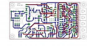
Any more concerns/ideas about Board#1 - I want to get it out to fab as it takes awhile ??
I added a cut to the ground planes so that the regulator and phono amp grounds are tied in one area only (and the top - underside ground planes are tied together with some vias at this point too) - I don't want ground currents from the two circuits inter-mixing.
There are two overlapping footprints for the input cap as I haven't decided between a 1uF film cap or a 10uF bipolar cap.
Attachments
Member
Joined 2009
Paid Member
The Quad 33 for all of it's faults has better than average tone controls. It's worth a look for inspiration. If one respects it's overload limits ( by testing ) it is remarkable how low the distortion is with so few components. It's phono input even if carefully arranged isn't it's best facility.
Member
Joined 2009
Paid Member
I like the simplicity of the Quad - the 'tilt' control that is. What I posted above can be set up as a tilt control, but instead of being 'neutral' when the tilt is set at the mid point, it can be arranged with some mid-scoop in the presence region. This is my thinking - since the tone control will be capable of being switched out of circuit I don't need it to be capable of neutral so it can be designed to offer some mid-scoop to reduce the 'presence' for those recordings/mixes where it's clear to my ears it's been over-done. Distortion should be low, using quality film caps for such filtering purposes. I'm not sure if I need the full range of adjustment that a tilt offers since I've never found myself wanting to reduce bass - increase treble on any of the music I generally listen to.
Member
Joined 2009
Paid Member
Don't need no gain
The tuner manual says output is "775mV / 2.2k" which tells me that I ain't needing to add gain.
hmmmm, I've run out of reasons to include the NAIM gain stage other than curiosity as to how it sounds. One reason might be to provide make-up gain after a tone control - but likely a high-impedance buffer is all I need. Well, perhaps no gain stage ?
replaying CDs and find that I don't need to change the vol pot when swapping between them.
The tuner manual says output is "775mV / 2.2k" which tells me that I ain't needing to add gain.
hmmmm, I've run out of reasons to include the NAIM gain stage other than curiosity as to how it sounds. One reason might be to provide make-up gain after a tone control - but likely a high-impedance buffer is all I need. Well, perhaps no gain stage ?
Member
Joined 2009
Paid Member
I prefer open loop, no stability concerns and generally simpler. I would think of two categories, a) single ended follower loaded on a current sink, b) diamond buffer, both of which maybe possible to set up so that the dc offset is stable enough to avoid the need fo any coupling caps.
Last edited:
I have a friend who is convinced buffers should give high power. 1 watt or more. This made me think why not have 1 watt 8R as it could be useful to have a preamp do that. He says usual buffers are not really doing enough. He is so convinced as to make me think he has a point. Maybe the low impedance is doing exactly the same as the voltage regulator in some situations. Most opamps get that low without the current so maybe not that reason. The D Self NE5532 power amp hints at this as an idea.
No, I have given up giving you advice on this project.Any more concerns/ideas about Board#1 - I want to get it out to fab as it takes awhile ??
I added a cut to the ground planes so that the regulator and phono amp grounds are tied in one area only (and the top - underside ground planes are tied together with some vias at this point too) - I don't want ground currents from the two circuits inter-mixing.
There are two overlapping footprints for the input cap as I haven't decided between a 1uF film cap or a 10uF bipolar cap.
I can't see any of it incorporated into your PCB design. Your priorities aren't the same as mine.- Status
- This old topic is closed. If you want to reopen this topic, contact a moderator using the "Report Post" button.
- Home
- Source & Line
- Analog Line Level
- TGMC - a modular control pre-amplifier