Member
Joined 2009
Paid Member
Phono - where to start ?
Just gazing around, there are hundreds of proven phono amplifiers out there. I'm just talking about MM and just discrete and the list is huge.
I wonder, if given good quality components, with attention to detail on the wiring, and a hi-end regulated power supply - is there much to choose between any of them ? I suspect that the reputation many of the 'famous' and historical designs have earned for themselves is partly from their choice of power supply and components that were available at the time they were in production. So such 'reputational' information is hard to rely on.
For me, I have no experience with an of them. However, I did get to the point of having the NAD3020 phono built (TGM1i) and briefly had a listen but nothing I can rely on. Since I have the parts on hand and have some design familiarity with this circuit it is on my short-list.
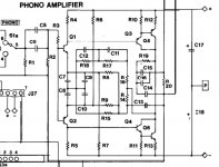
The Naim looks messy in comparison. The MM stage has a pure gain stage feeding an RIAA corrector. It's still not enough gain and relies on the line-amp gain stage to provide decent signal level. That's a lot of transistors and other parts for the signal to traverse.
The DH-101 design looks nice. I read it might have been a Borbely design. It has simplicity and elegance.
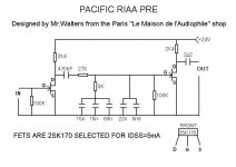
If we accept the use of JFETs (SMD parts are the most available) it opens up a whole extra list of possibilities. I'd favour the Salas Simplistic because it's been so well documented and tested through builders on this forum.
And I'm aware that an op-amp based circuit with modern op-amps should be flawless in performance. So my somewhat subjective short list becomes (in no particular order):
> NAD3020 (BJT, discrete)
> DH-101 (BJT, discrete and symmetrical)
> Salas Simplistic (JFET, discrete with a tube-like topology)
> Op-amp based (i.c.)
Thoughts ?
Edit - p.s. there's a nice thread on a super-simple design with the historical information that makes this hobby fun: http://www.diyaudio.com/forums/analogue-source/158918-2n2222a-phono-preamp.html
Just gazing around, there are hundreds of proven phono amplifiers out there. I'm just talking about MM and just discrete and the list is huge.
I wonder, if given good quality components, with attention to detail on the wiring, and a hi-end regulated power supply - is there much to choose between any of them ? I suspect that the reputation many of the 'famous' and historical designs have earned for themselves is partly from their choice of power supply and components that were available at the time they were in production. So such 'reputational' information is hard to rely on.
For me, I have no experience with an of them. However, I did get to the point of having the NAD3020 phono built (TGM1i) and briefly had a listen but nothing I can rely on. Since I have the parts on hand and have some design familiarity with this circuit it is on my short-list.
The Naim looks messy in comparison. The MM stage has a pure gain stage feeding an RIAA corrector. It's still not enough gain and relies on the line-amp gain stage to provide decent signal level. That's a lot of transistors and other parts for the signal to traverse.
The DH-101 design looks nice. I read it might have been a Borbely design. It has simplicity and elegance.
If we accept the use of JFETs (SMD parts are the most available) it opens up a whole extra list of possibilities. I'd favour the Salas Simplistic because it's been so well documented and tested through builders on this forum.
And I'm aware that an op-amp based circuit with modern op-amps should be flawless in performance. So my somewhat subjective short list becomes (in no particular order):
> NAD3020 (BJT, discrete)
> DH-101 (BJT, discrete and symmetrical)
> Salas Simplistic (JFET, discrete with a tube-like topology)
> Op-amp based (i.c.)
Thoughts ?
Edit - p.s. there's a nice thread on a super-simple design with the historical information that makes this hobby fun: http://www.diyaudio.com/forums/analogue-source/158918-2n2222a-phono-preamp.html
Attachments
-
 322 board schematic.jpeg54.2 KB · Views: 478
 -
 Marantz SR2285B phono.png39.9 KB · Views: 196
 -
 SE JFET RIAA.JPG257.6 KB · Views: 199
 -
 Schema_3020_phono.gif13.9 KB · Views: 191
 -
 salasriaa2sk170bl.jpg76.8 KB · Views: 191
 -
 pacific-RIAA.JPG36.7 KB · Views: 187
 -
 Boozhound-Labs-JFET-Phono-Preamp-Kit-Schematic.png33.5 KB · Views: 372
 -
 high_octane_sch_bw_s_corr2-web.jpg101.8 KB · Views: 454
 -
 DH-110 MM Phono.jpg102.6 KB · Views: 458
 -
 DH-101 MM Phono.jpg242.3 KB · Views: 473
Last edited:
Lots of books and semiconductor company application notes, point out that for MM phono cartridge amplification with 47K input impedance, JFET inputs give the lowest noise. Whereas for MC cartridge amplification with <10 ohm input impedance, BJT inputs give the lowest noise. Some people work very hard to get extremely low noise, others say ppphttbbphtbbtpt (Bronx Cheer), I'll do what's easy. Sure, the noise won't be lowest but it'll still probably be okay.
Me personally, for MM inputs I favor an opamp built out of discretes (with JFET input), running on higher voltage rails: ±25V. This guarantees plenty of "overload margin" and plenty of reverse bias on all B-C (or G-D) junctions, so the junction capacitances are reduced and their nonlinear C-vs-V properties are also reduced. Samuel Groner's HVA (link to pdf) is one representative example.
There's also lots of love for the Advent Receiver's MM phonostage (designed by Tom Holman) and the Apt Preamp's MM phonostage (same designer). I happen to think that Nelson Pass's NS-10 phonostage from 1977 (4 BJTs + DC servo) is delightful but this is a minority opinion.
Member
Joined 2009
Paid Member
Some people work very hard to get extremely low noise, others say ppphttbbphtbbtpt (Bronx Cheer), I'll do what's easy. Sure, the noise won't be lowest but it'll still probably be okay.
Sometimes it is as easy as choosing the right transistor
") (tho putting it to work in a given circuit often requires skills) But most people do not realize this. Probably because they cannot hear the difference.
(tho putting it to work in a given circuit often requires skills) But most people do not realize this. Probably because they cannot hear the difference.I'll give you all an example to think about...
Most people use transistor with Vce of half the supply rail (for safety reason). But there are many great transistors with very low Vce. Let's look at NAP250 where power supply is =/-40V. What is the Vce of the input transistor (BC239c)? 25V!!
Such can only happen when the designer understand what difference it can make to the sound (same like ZTX 384c/ZTX214c used in Naim pre).
There are many quality area in sound reproduction. My favorite one is a rare quality area. I have never heard it except from my own amps. And if that quality is exist in Naim then without using the right transistors no one will ever achieve it. It requires the right transistors to begin with.
Modern transistor to replace BC239c in NAP250 is BC550c. But BC550c is not as good as BC239c. I don't know what other transistor can outperform BC239c, except my favorite, which is as old and rare as BC239c. It is 2SC1815BL (Tho to fully realize its potential in term of noise, this transistor needs low current, which might be unsuitable for NAP250 topology. But that extra-ordinary low noise capability doesn't have to be pursued).
And then there is that thread on Bigun's last post about 2N2222. I think some people can really hear what difference this transistor can provide. Unfortunately not all 2N2222 can do it. I have gold pin 2N2222 transistors where 30% weren't good enough.
> Op-amp based (i.c.)
Thoughts ?
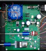
The preamp that I have built for myself is IC based (LM4562) . I love it as much as I love my tube amp. I wanted shorter signal path around the ICs and designed the audio circuits with SMT.
I went through several stages from breadboard to switching between passive and active circuit etc. In the end, it's the active version that I designed on the PCB, and I'm glad that I did, because for some power amps (tubes) sometimes you'll need the gain. The preamp is basically buffered motorized and remote controlled volume control with a little gain after it. I use two ICs in parallel in every stage to decrease the circuit's own noise (by Self).
I don't think a DIY effort with discrete devices can beat a properly designed circuit with OP amps. Surprisingly, I don't hear it at all in my setup. It gives me the comfort of the remote and the pre-amplification without adding anything to the sourced signal.
No RIAA only line inputs, though. But I think for RIAA is even easier to get better results with ICs.
Attachments
This is a good thread as it general and not just about a Naim clone.
As to shunt regualtors. No23 link shows why a series regualtor might have problems. I designed a series regulator for a friend where we tried to make it all things to all men and we used a really odd idea. The circuit was ultra simple. FET source followers using IRF540 and IRFP9540 as they were what I had in the junk box.
The voltage reference was a zener with filter cap and constant current source feeding it. There was a series resistor to fine set voltage. The filter cap set by ear and measurement.
The really weird bit was alowing very bad ripple in the 10 uF polyester reservoir cap. Looking at the output it was fine.
Here is the conjecture. The FET is very nearly a resistor, not least at 120Hz. It is only dealing with harmonics to lets say 1 kHz from the ripple, certainly not 100 kHz due to ripple. I wouldn't know the exact speed of the FET except to say many 10's of MHz. To my mind this is the variant of a series regulator that can not be pushed to one side.
The most interesting thing is Gary who I made this for never went away from the 10uF. He felt he could hear the capacitor through the FET. Logic says he might be right. There was minute hum ( - 93 db reference 12 V ). The circuit had very good rejection and non was every heard. Gary is hyper fussy so would have said if there was. If using a descrete op amp even the voltage adjustment could be avoided as most regulators would be lets say 18 to 20V without adjustment, or whatever you want.
The bigger surprise of this was that the prototype amplifier used SMD NE5532 op amps which no one in the world loves ( publicly ). Previously that part of the circuit wasn't thought to be the best. After the PSU the 5532 was found to be rather wonderful and very transparent ( yikes ). The reason I suspect was it's output current. It was nearly that the numbers were removed and went into production. Along the way OPA2604 was tried and was rejected. I forgot the choice that was settled on. It was mostly to please the curious. I can't say if 5532 needs this PSU, seems it might. For most uses I prefer MC33078/9 if in the bargain devices area.
Remember. The regulator follows the needs of the op amp. This FET idea might show minute 2nd harmonic if you look hard enough ( battery against PSU ). Not the worst thing to have. My conjecture is the FET is faster than the op amp and that's the maths to satisfy. It must be stable and not add too much. What most critics of these circuits run away from is 90% of the reality of how this works is the decoupling next the the op amp or whatever. I only recently found out ( ? ) that the slightly lower grade ceramics below NPO/COG do the best job. Their imperfections being ideal. I have doubts about that and might use a mix of types. If you put a very high grade scope near the op-amps in a CD player you might get a big surprise. Right up to the chip nothing looks to be right. Then at the last moment it looks a lot better. I had a very small hand in the first Naim CD player. It has tons of PSU's. It is still to this day one that sounds better than most and most Vinyl. My part was convincing Julian to do it and falling out with Paul Stephenson for doing that. My arguement was if Julian built it then he would know the truth. My words were " Regardless of what you think Julian you could make the best CD player in the World ". To which Julian said " That would be the easy bit....... You know ( looking at Paul ) we thought FM radio was no good until we built one". That killed it between me and Paul as I was told to leave Julian alone that day. Julian was hyper depressed as it was the day Linn USA no longer distributed Naim, ironically a good time to talk. 21 PSU's using selected LM317's I think ? My hyper beautiful wife Fabienne was his real focus that day, we obviously had similar tastes. Well done Fabienne you helped make the CDi or whatever we call it. For historical balance I liked the Meridian 14 bit players almost as much. Apart from Quad CD67 I lost interest after that. I believe the 67 was the work of the designer of NAP200, he says a minor team memeber only.
I had an Exposure amp to fix with up and down stream regualtors. It had bad troubles when the scope was used. I replaced the up device with a RC filter. It was much better and no more oscillations. There was a desgn error in that amp which Self talks about. That was induction hum into wires. That was getting in to regulator section one in the main amp. I got rid of 90% of it. At the final stage I had two null points. One that gave lower lumped figures and one that gave more 50 Hz and less 100 Hz. The latter gave a much better sound. I can see why. I never knew it before that. Mid band detail if asking.
Dedegogo. The BC239 point is a good one. I often wondered if a resistor in the tail was an idea as on paper the Vceo looks too small ( I forget all of the details ). Others have written on this so I defer to the fact that it has worked.
I really wonder if a descrete op amp based on NAP could be used as our " NE5534". It could for fun have a version of 1K 22K LTP. Weird types like 2N4401/3 BC327/337 are interesting. The 2N's are like diesel engines that seem OK! They were really switching types. Rbb' I suspect can win the day. Makes me laugh when people say one transistor is more linear. If compared with pentodes that is valid. As current amps transistors are rather wonderful. Strictly speaking only the TIS or VAS is in that linearity question. If the input pair sound different it should be rbb' or gain. Someone told me that the spectrum of noise transistor or pentode favours pentode ( not white box USSR ones ). He went on to say if transistors have almost no noise suddendly warmth in the sound is heard. That seems OK to me. One has bandwidth limit also to think of.
BTW. If one looks at EF86 it has about 0.1% THD with a massive voltage swing in fake triode. However in pentode the distortion is not much more when used for a microphone. The reason being the part of the curve used is very small. Looking to NE5534 and EF86 at gain 100 I was surprised to find the distortion of the EF86 for a small signal was not very different. The really tough bit is the output impedance is 470K typical ( hiss and matching problems ). However if fed into a OPA604 which can be close to infinity no problem is seen. Then some idiot will say " you prefer it because you like the distortion, you like a box of crayons". But, there is no distortion and very little hiss. Such hiss that a Mullard EF86 has is slightly nicer than a NE5534. Many recordings to this day have pentodes in the microphones. Sometimes some noise is a friend. It is often guessed that -66 db is the real hiss levels of a system. Before dither it's all we had to rescue digital. The right type of hiss can actually help class B be more linear. Crossover distortion is much like bad digital. As transistors don't really have nice hiss, better to bias the class B correctly ( whatever that might be ). For a descrete op amp class A is what we can have . SE or PP, it's our choice. Remember Naim was class A SE.
Member
Joined 2009
Paid Member
Nigel, you are a goldmine of information. Very interesting. Do you fancy writing a book ?
I'm leaning towards a have-my-cake and eat it approach. Design a pcb with two parallel RIAA amps. One of them will be a traditional through-hole discrete design. The NAD or the DH perhaps. The other will be an smt op-amp design. This is DIY afterall and the last thing I have in mind is to make it a commercial style engineering project. So two amps on one board to provide the ultimate choice and learn something with my own ears. What do you think ?
I'm leaning towards a have-my-cake and eat it approach. Design a pcb with two parallel RIAA amps. One of them will be a traditional through-hole discrete design. The NAD or the DH perhaps. The other will be an smt op-amp design. This is DIY afterall and the last thing I have in mind is to make it a commercial style engineering project. So two amps on one board to provide the ultimate choice and learn something with my own ears. What do you think ?
Do you have a schematic of your line stage that you can share ?The preamp that I have built for myself is IC based (LM4562) . I love it as much as I love my tube amp. I wanted shorter signal path around the ICs and designed the audio circuits with SMT.
Last edited:
Good thread and not really just for Naim people.
Op amps in SE class A would give a Naim sound on the cheap. First trial, fix a 10 K resistor from op amp out to -ve rail ( or + ve, it will sound slightly different so worth seeing what you like ). If you like it try a CCS. I found the low levels work well with this. An RIAA, stage one in SE class A and output stage two in normal PP class AB. The old 741 work well with SE class A, or rather it worked badly in PP AB.
I did try the pull down resistor with a class AB power amp once. It needed to be too large to be practical. The idea being to get 1 watt in class A.
Do you have a schematic of your line stage that you can share ?
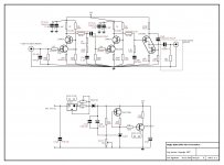
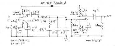
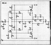
Yes, sure. Find attached. As I said, it's absolutely standard circuit and in my opinion the very good sound and operation comes from the SMT, the fact that the pot is buffered and that I generally used lower resistor values to reduce Johnson noise. According to Self 4 Opamps in parallel are about the optimal for quality/price/noise. I used just 2.
I might have an error in this schematic in wiring the potentiometer that I corrected later, due to misunderstanding of top/bottom view.
Attachments

Here is my fake Naim sound idea that is very cheap to do. What the pull down resistor does is mimics the distortion types of the Naim original. Put in capacitors as you think fit. Some shown for guidance. Buffer gain might be 1. Needs some connection to ground on input not shown.
The big deal is the resistor can be in a connector block to allow testing. With or without it works. Op amp DIL holder also as many can be tried. The resistor can be replace with a constant current device if you like the idea. The buffer could have it.
MC33078/79 being a Naim like sound. Slightly better to my ears. Most designers assume all know this trick. Some might not.
Member
Joined 2009
Paid Member
Thanks Ruwe - I'm not sure I know what all the parts are as shown thoughYes, sure. Find attached.
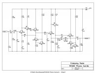
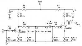
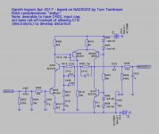
Attached is my current favourite on the MM phono amplifier. I think it has very good on-paper performance and a very good reputation (comments made earlier not withstanding). I have also increased the gain over the NAD original so that further gain is not required. Simulation results are very encouraging, with low distortion, decent PSRR and no obvious concerns about overload tolerance.
Please see also some information from 'andyc' who used to be an able member of this forum: Andy's Audio and Electronic Design Topics
Attachments
Last edited:
Thanks Ruwe - I'm not sure I know what all the parts are as shown though
Sorry, not intentional. That's what I have, because I'm lazy and I know I'll build SN0001, and maybe SN0002 if a friend of mine also wants one
The main mysterious parts are the Grayhill selector switch and the motorized Alps 22k quad-potentiometer between the stages.
I'm familiar with Grayhill from my years in avionics repairs. They are widely used as encoders by many companies and I find them amazingly reliable. They can stand dozens of years of abuse by pilots pushing, wiggling and hitting them countless times. The downside that I found later (which is valid for any rotary switch IMO) is that they have some crosstalk. So, relays are still probably a better option, although this switch most likely has better contacts than most.
The switch has three poles and the return (ground) lines of the sources are switchable too. I think, this is very important in avoiding the preamp to become a crossroad of ground loops. Still, many people switch just the signal lines. I guess this is the way of thinking that currents magically disappear when they reach the common.
There is also an H-bridge shown that controls the rotation of the 5V motor of the Alps by remote. The remote control receivers I buy online from a guy in the Netherlands. Very small and simple board that works with Philips and Sharp codes.
Last edited:
Member
Joined 2009
Paid Member
Sounds really good !
I have been shy about remote control - I figure the lack of one will get me off the sofa once in awhile
[note error in my attached diagram 2 posts back. It should say '... instead of allowing C410 the feedback shunt cap...'. The idea is to avoid allowing any electrolytics in the signal path do any low-pass or high-pass filtering and leave that job instead to higher quality caps]
Last edited:
Member
Joined 2009
Paid Member
Do I need a gain stage for line inputs ?
Now I'm scratching my head as to why I would want any line-stage gain. I don't expect to have a source that puts out feeble voltage levels. A unity gain buffer offers a lot of benefit, but I'm not seeing the need to provide gain. My power amps all provide 24dB to 28dB of voltage gain already. Not saying I won't include gain - do you find yourself needing extra gain ?? (or do you have the volume control rarely past 1/4 turn)
I have also increased the gain over the NAD original so that further gain is not required.
Now I'm scratching my head as to why I would want any line-stage gain. I don't expect to have a source that puts out feeble voltage levels. A unity gain buffer offers a lot of benefit, but I'm not seeing the need to provide gain. My power amps all provide 24dB to 28dB of voltage gain already. Not saying I won't include gain - do you find yourself needing extra gain ?? (or do you have the volume control rarely past 1/4 turn)
Last edited:
I have been shy about remote control - I figure the lack of one will get me off the sofa once in awhile
Tell me about it!
I found also very useful to have two preamp outputs. In my case I can short or split the output of the paralleled ICs in the last stage. E.g if you want to send one of the outputs to a subwoofer summing input, or if you want to switch easy between outputs with different gains. Or, if you have two separate audio systems that you need to switch between easily.
You are in design phase, so some added features might be useful to add. After all the reason to consider a preamp (except the RIAA) is to give more flexibility than straight connection from the source to the power amp.
I use tube amp and I need the gain.
Right now I believe that my final resistors choice in the preamp gives me about 4x of gain. I listen to about 10 o'clock for comfortable, but not loud sound level in our living room from my not very efficient speakers.
Also have in mind that many recordings are quiet. At least, well recorded classical music is.
Another, not very rational, reason is that sometimes more gain kind of makes the sound more alive and dynamic. It doesn't make much sense, since you can say "what about turning the volume control more?" . But there is something that is not equal between same loudness from circuit with gain and without. I'd love if someone have a good logic explanation about that. That's why I always find passive "preamps" veiled... And it's not just the higher output impedance of the lonely potentiometer, because it isn't that bad at maximum or minimum setting.
Member
Joined 2009
Paid Member
That is similar to my experience back when I found my Bryston amp, pre-section, provided good results when I used it as a volume control for my DIY amps. Subjectively, it provided a very 'solid' sound.But there is something that is not equal between same loudness from circuit with gain and without. I'd love if someone have a good logic explanation about that.
Hi,
just cross-read but thought that the TO mentioned a modular concept right at the beginning.
50 posts later and there's still no drawing of a concept but already thoughts about certain parts and circuits
If the TO for example insists on the possibility of a non-powered passive play mode this will seriously reduce the amount of options.
If powered passive mode is an option almost all wishes can be mastered.
You may have a look at my website, where two preamps -both modular concepts- are described.
The Calvin Pre is a rather classic active topology, featuring seven relais-switched inputs, of which two are tape loops, a volume control poti, a output drive stage and a headphone driver (optionally switch-on, separate volume poti).
The Inputs, Tape loops and Output drivers are mounted on PCB cards that connect to a mainboard via 31-pin DIN41617 connectors.
The Input cards can be of any kind, neutral, Phono, etc...
The mainboard mostly consists of a bus system of audio-, supply- and control signal lines (external PS, control logic PCB connected via flatband cable).
In a 1-box Pre the motherboard could also house the power supply and control logic (the latter could still be a fly-out PCB mounted behind the front).
The design of the audio circuitry is then restricted only by the number and voltage level of the supply lines, the number of audio signal lines and the number of control signal lines.
The purist Pre is also a modular concept but different.
It is rather a passive preamp utilizing a input selector for six inputs (3x RCA, 3x XLR, two of the Inputs can optionally be equipped with Phono-Pre cards) and a switched resistor volume control (constant, low output Z).
To allow for se-to-balanced conversion and/or 0/+6dB gain a 6dB-gain stage can be switched into the signal path with relais.
A optional output cable driver can be switched into the signal path behind the VC with relais also.
The Phonos, Balancer and Output driver come in form of cards again to allow for testing different circuits.
Due to the amount of relais for signal routing and in the VC-circuitry a uController is required, also allowing for IR-remote control capability and display visualization.
It seems to me, that a combination of both concepts could be just what the TO is looking after.
I suggest that You sketch and develop the whole concept first, divided into blocks/subassemblies and how they are to be connected, taking into account the required or wished-for flexibility.
When You opt for a motherboard and push-in card system You can think about circuit schematics or certain parts at a later stage of the development process.
jauu
Calvin
- Status
- This old topic is closed. If you want to reopen this topic, contact a moderator using the "Report Post" button.
- Home
- Source & Line
- Analog Line Level
- TGMC - a modular control pre-amplifier