I'm running +/- 12v to the TL074 so that shouldn't be the problem then. Maybe it's just too much Q for that circuit like you said. At the time I had it set up for 165 Hz with a Q of 6.
It's really not a problem though, as I found I can get enough done on the sub with just two all-pass filters.
It's really not a problem though, as I found I can get enough done on the sub with just two all-pass filters.
Well I've got this all assembled and installed, although there are still a few things I could use help on:
1) Should I make an effort to have a specific input impedance? I believe all that would entail is a resistor to ground installed upstream of U1 on the signal wire. I don't know the output impedance of the 3sixty.3 DSP that's upstream.
2) Should I make any efforts to block DC at the input to the circuit?
3) I have a hefty turn off pop from the subwoofer. It was doing both on and off pops but the 3sixty.3 DSP allows you to delay the amp turn on so I added 2 seconds there and resolved the turn on pop. The mids don't pop during turn off, only the sub does, so I assume it's related to the larger capacitors. Any thoughts on how to fix that?
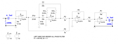
Just as a refresher, this box contains two 2nd order all-pass filters on one board (one for each 6.5" midrange), and two cascaded 2nd order all-pass filters for the subwoofer on the other board. The small board is a DROK dual voltage power supply set to +/- 15V.
1) Should I make an effort to have a specific input impedance? I believe all that would entail is a resistor to ground installed upstream of U1 on the signal wire. I don't know the output impedance of the 3sixty.3 DSP that's upstream.
An externally hosted image should be here but it was not working when we last tested it.
2) Should I make any efforts to block DC at the input to the circuit?
3) I have a hefty turn off pop from the subwoofer. It was doing both on and off pops but the 3sixty.3 DSP allows you to delay the amp turn on so I added 2 seconds there and resolved the turn on pop. The mids don't pop during turn off, only the sub does, so I assume it's related to the larger capacitors. Any thoughts on how to fix that?
Just as a refresher, this box contains two 2nd order all-pass filters on one board (one for each 6.5" midrange), and two cascaded 2nd order all-pass filters for the subwoofer on the other board. The small board is a DROK dual voltage power supply set to +/- 15V.
An externally hosted image should be here but it was not working when we last tested it.
Can you post a pic that is more clearly legible?
1.)
The first active stage has a small requirement for input offset current (it's in the specification for the opamp, you need to calculate it for a discrete stage).
This offset current must have a route back to the power supply.
Rin usually provides this route. Omit Rin and the active may not work.
Note that in the pic nine of the opamp input pins have a connection that can pass input offset current to some other pin that ultimately connects to power. The input pin relies of the ZERO source impedance of the theoretical voltage source to pass this offset current. Disconnect that DC route (by adding capacitor coupling) and the circuit will not work.
2.)
If an excess of DC will interfere with the operation of the circuit, then yes you must limit the level of DC.
If the next stage is affected by an excess of DC, then yes you must limit the level of DC.
3.)
Adding an output mute that triggers on loss of AC (switch OFF) helps prevent untoward effects downstream.
Last edited:
Sorry about that small schematic pic, here's a bigger one:
And the link just in case: https://goo.gl/photos/SSwZPcsSMm5HTBLD8
Thanks for looking into my questions. Here's what I'm thinking now:
1) I believe the TL074 is internally compensated so I don't need to be concerned with offset current. The AD paper MT-038 advises to compare Input Offset Current and Input Bias Current, and if they are the same magnitude then the op amp is internally compensated. That seems to be the case with the TL074.
In looking through old patents I saw where the BBE circuit used a TL072 and for the input buffer they had a 1uF cap in series followed by a 100K resistor to ground.
2) I don't really know if an excess of DC would interfere with the circuit. I do know that the upstream DSP source was previously applied directly to the downstream amp with no problems, so I felt that the signal would be free of detrimental artifacts. I've got some 2.2uF caps on hand and could add them no problem.
3) Some sort of mute would be great, but how would I add something like that?
Thanks!
An externally hosted image should be here but it was not working when we last tested it.
And the link just in case: https://goo.gl/photos/SSwZPcsSMm5HTBLD8
Thanks for looking into my questions. Here's what I'm thinking now:
1) I believe the TL074 is internally compensated so I don't need to be concerned with offset current. The AD paper MT-038 advises to compare Input Offset Current and Input Bias Current, and if they are the same magnitude then the op amp is internally compensated. That seems to be the case with the TL074.
In looking through old patents I saw where the BBE circuit used a TL072 and for the input buffer they had a 1uF cap in series followed by a 100K resistor to ground.
2) I don't really know if an excess of DC would interfere with the circuit. I do know that the upstream DSP source was previously applied directly to the downstream amp with no problems, so I felt that the signal would be free of detrimental artifacts. I've got some 2.2uF caps on hand and could add them no problem.
3) Some sort of mute would be great, but how would I add something like that?
Thanks!
Ok that makes sense.
Last night I added a 21.5k resistor to ground at the input buffer of each circuit, as well as a 10 uF cap between V+ and V- just to make sure there aren't any issues related to decoupling.
After those mods there is audible clipping on higher frequencies. I'll switch those 21.5k resistors for 1M units tomorrow and see what happens.
It seems like the forum limits the width of pics, so that's making it hard to show a nice clean schematic. But I made a direct link to it in the last post, just click that and you'll be able to see it better. I'll keep trying though.
Thanks for your help!
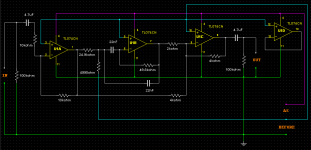
Here's the schematic for the left side. The right is similar. These are the ones where I'm noticing the higher frequency clipping now.
https://goo.gl/photos/STniGjP6CM1xYg1E9
An externally hosted image should be here but it was not working when we last tested it.
https://goo.gl/photos/STniGjP6CM1xYg1E9
Last edited:
Based on the info I'm reading on Rod Elloitt's site, both the turn off pop and the clipping may be due to DC issues.
http://sound.whsites.net/articles/coupling-caps.htm#p10
My next move will be to add 0.82 uF caps to the input of each mids circuit, and a 2.2uF cap to the input of the subwoofer circuit. I'll report back on how that goes on Saturday.
http://sound.whsites.net/articles/coupling-caps.htm#p10
My next move will be to add 0.82 uF caps to the input of each mids circuit, and a 2.2uF cap to the input of the subwoofer circuit. I'll report back on how that goes on Saturday.
Zero D, what is the function of the resistor to ground before the input decoupling capacitor?
At this point the largest high quality resistors I have on hand are 82.5k, so I swapped the 21.5k for 82.5k and added an input decoupling capacitor. I'll have to go shopping for something to use on the output side though.
On the scope I ran each section with about 3V sine tones from 50-10k Hz and there's no clipping or abnormal behavior visible.
Installed in the car the results when listening to music are identical to the previous ones, in that there's distortion on long/low/loud bass notes, and clipping on higher (1-3k) frequency tones.
Here's the latest version of the left side circuit (click to view):
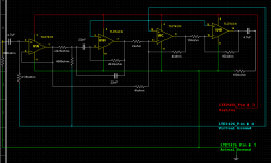
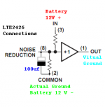
Ok i've simmed it. First off, as i mentioned, make SURE that your Actual Ground connections are correct, as i've shown in Green. And that your Virtual Ground connections are as i've shown in Blue. Otherwise you will get wierd results !
Are you making use of the noise-reduction pin with a capacitor between Pin # 8 & Pin # 2 ? If not you should. Try a 100uf electrolytic & observe the Polarity !
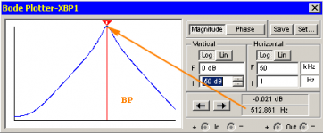
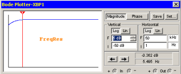
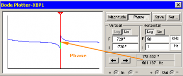
Next, your filter is actually a Bandpass peaking at around 500Hz. See my bode plot of it. The final frequency response output of the circuit is also shown. So you're getting a 180 degree phase shift centered around 500Hz, which decreases in phase either side of this point, mixed with the original signal. I guess this is what you want.
Are you making use of the noise-reduction pin with a capacitor between Pin # 8 & Pin # 2 ? If not you should. Try a 100uf electrolytic & observe the Polarity !
Next, your filter is actually a Bandpass peaking at around 500Hz. See my bode plot of it. The final frequency response output of the circuit is also shown. So you're getting a 180 degree phase shift centered around 500Hz, which decreases in phase either side of this point, mixed with the original signal. I guess this is what you want.
Attachments
No wonder I was confused by your statement
The Blue trace connects the Audio Ground/Return.
The green trace connect the Power Ground.you have components connected to the Actual Grounds & the Virtual Grounds connected incorrectly ?
The Blue trace connects the Audio Ground/Return.
Thanks for taking a look at this with me guys.
Since I ran out of space on the protoboard I couldn't fit the LME2426 setup, even though I think they are very cool. I'll save them for my next project - they worked great on the big breadboard I had, and I had included the noise control cap and a second cap that gave it a bit of a soft start.
I went with a little breakout dual voltage board you can find on ebay for about $8 just to save time.
HIFI Low Noise Single Voltage To Positive Negative Regulated Power Supply Module
I've adjusted it to provide a -15V and +15V output and it works great. I do hear a small amount of lower frequency engine noise coming through the mids though, so I'll have to address that eventually.
After reading about the evils of non-inverting op amps (Inverting vs. Noninverting | EDN skip to the end for the quick answer), I decided to chop off the last stage which was just there to invert the signal back to normal. In order to inverted the signal then I swapped the leads at the output RCA, so the ground became connected to the center pin and the signal from the circuit was connected to the shield. I don't know if that's an acceptable practice, but it seems to work with no adverse effects.
I finally found a good reference for resister values in the inverting summing amplifier section on Rod Elliott's page (Audio Signal Mixing)
and decided to switch the 4k and 2k values I was using to 10k and 5k respectively.
Then I scavenged some Elna 3.9uF 25V audio grade bipolar caps to install in the outlet of each circuit to block DC.
I'm almost done with those mods and will let you know what the outcome is.
AndrewT
The green trace connect the Power Ground.
I thought that would obvious. It also connects the Input Grounds from the feed signal audio, & the Output Grounds to the next stage, Amplifier.
The Blue trace connects the Audio Ground/Return.
The Blue ONLY connects things to the Quasi Ground = Half Supply = 7.5V You do NOT connect the In/Out Grounds from/to other equipment to the Blue !
@ mojozoom
Ok, so you have the -15V and +15V board in place of the LME2426. You still need to connect that supply as i've shown for the LME2426, & mentioned just above !
I decided to chop off the last stage which was just there to invert the signal back to normal.
I wouldn't
In order to inverted the signal then I swapped the leads at the output RCA, so the ground became connected to the center pin and the signal from the circuit was connected to the shield. I don't know if that's an acceptable practice, but it seems to work with no adverse effects.
That's just Wrong ! Change them back, & include the last stage, or convert UA1 to inverting & don't use UA4, as shown. This achieves Exactly the same result
")
Attachments
Yeah, now that I think of it, if ground on the amp is connected to ground on the filter, then connecting the signal to the ground on the amp should cause everything to go very badly. But it doesn't in this case. Three cheers for JL Audio amps saving my butt once again.
So I'll fix that issue tonight. I've got all the other mods made and just need to run it on the bench scope to make sure all is well before I plop it back in the car. I'm still going to eliminate the evil inverting stage though in the interest of keeping noise as low as possible.
Since both mids are going to see a phase inversion I'll either invert the wiring to the drivers or invert the signals via the DSP so they line up with the sub and the tweets again. Hopefully things tonight will go well enough that I can run some phase tests with everything installed.
Ok here's more detail on this saga.
At this point the mids circuits are working very well. There's a slight amount of engine noise noticeable at idle, not a whine but a clicking, very faint. I assume it's tied to spark pulses, but haven't tried to dig into how to filter that out.
The subwoofer circuit has been a learning experience. There I have two all-pass filter in series, but the interesting novelty is that only the first one works. After some research I've found that I had my thinking backwards, and that the lowest Q filter has to come first. I'll make that change later this week and hopefully then both filters will apply as expected.
I still have a turn off pop on the subwoofer, but I'm going to try some caps on from +V to GND and -V to GND to slow the rate that the voltage ramps up and down to the circuit.
So we're not out of the woods yet, but close.
@ mojozoom
Yeah, get the engine noise sorted.
Try without any input, & the volume turned right down on the amp. If it still does it, then it's an issue with the amp. If that's ok, then it's one or more things before the amp.
What, on the amp or filter ? Either way it won't prevent the pop. Anyway i'll wait till you post back with further info
Yeah, get the engine noise sorted.
I still have a turn off pop on the subwoofer
Try without any input, & the volume turned right down on the amp. If it still does it, then it's an issue with the amp. If that's ok, then it's one or more things before the amp.
.but I'm going to try some caps on from +V to GND and -V to GND to slow the rate that the voltage ramps up and down to the circuit
What, on the amp or filter ? Either way it won't prevent the pop. Anyway i'll wait till you post back with further info
The amps don't have volume controls - they're fixed gain car audio amps. That's really not a big deal though as I know that the noise is coming from the filter circuit box that I made. Everything else in the audio chain has been there for at least 2 years and there was no noise before I put the filters in there, and there is no noise when I take them out. I've had them in and out of the car about 20 times now testing different changes.
I'm sure the amps and the DSP have built in filter circuits to clean up any noise on the power coming in, and I just need to do the same thing. I've ordered a choke and a good sized cap to build a filter right where the power enters the box. But over lunch I finally added up all the current flow and I don't think the choke I ordered can handle it. Oops.
But I have good news on the turn off pop eliminator caps - they worked great. The turn off pop has gone from LOUD to just barely perceivable. The caps keep voltage on the filter circuits for about 1/2 second after you turn of the key, so the amp shuts off before the filter circuit does. Larger caps would be better I suppose, but I don’t really have the space for it in the box.
- Status
- This old topic is closed. If you want to reopen this topic, contact a moderator using the "Report Post" button.
- Home
- Source & Line
- Analog Line Level
- Active all-pass filter design questions