there's a 100K resistor that comes from 6SN7 cathode 1 and connects
to the top of the 100K plate resistor. I've seen no such technique in the
books and online articles I've consulted.
Sending DC current into the cathode resistor is a partial fixed bias.
It's a way to use a smaller cathode resistor than the DC bias point
would normally need, for higher AC gain without a bypass capacitor.
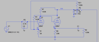
The diagram has the R21 (100k) in parallel with the R4 (522k). This is not likely.
Last edited:
Thanks, rayma.
R4 (522K) goes from pin 6 (K1) to pin 2 (P2).
R21 (100K) is weird. A wire goes from pin 6, to the "Lo" row of the Hi/Lo gain switch, to a tag strip where R21 connects to R7 (the other 100K). The components in the "Lo" row of the Hi/Lo gain switch are connected at all times. (The "Hi" row, when selected, adds a resistor of undeterminable value to a cathode bypass capacitor for K1.)
Looking more closely, technically speaking R21 also connects to the low end of dropping resistor R5 (2K) and its two capacitors (C3, C4) that go to ground, as in the revised attached schematic.
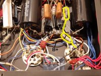
I also added an annotated picture inside the amp, where you can see the two 100K resistors in series outlined in yellow. The 2K resistor that shares the connection is R5.
R4 (522K) goes from pin 6 (K1) to pin 2 (P2).
R21 (100K) is weird. A wire goes from pin 6, to the "Lo" row of the Hi/Lo gain switch, to a tag strip where R21 connects to R7 (the other 100K). The components in the "Lo" row of the Hi/Lo gain switch are connected at all times. (The "Hi" row, when selected, adds a resistor of undeterminable value to a cathode bypass capacitor for K1.)
Looking more closely, technically speaking R21 also connects to the low end of dropping resistor R5 (2K) and its two capacitors (C3, C4) that go to ground, as in the revised attached schematic.
I also added an annotated picture inside the amp, where you can see the two 100K resistors in series outlined in yellow. The 2K resistor that shares the connection is R5.
Attachments
Last edited:
@Jeff possible you'll receive more help in the Tubes / Valves sub-forum http://www.diyaudio.com/forums/tubes-valves/
Could you ask mods to move the thread.
Could you ask mods to move the thread.
So, I have a version of this amp running now, and it sounds good. The only problem is that the power transformer is getting excessively hot. I believe this is due to current on the 6.3V heater chain.
My PT has a 6.3V/4A secondary.
I had the 6EM7 (925mA) and two 6SN7s (600mA ea.) wired in parallel on a chain, with AC heating on the 6EM7 and DC on the 6SN7s. I didn't realize at the time that converting AC to DC essentially doubles the current draw. So I'd been getting 925mA + 2(2 x 600mA) = 3.325A (more than 83% of a 4A winding).
I tried changing the 6SN7s to AC heating (2.125A draw on a 4A winding). It runs cooler but the hum is way too loud. So I have two questions.
* If I try using hum pots on tubes that are paralleled in a chain, should I use one pot per tube or would one pot somewhere in the chain suffice? I'm not sure if adjusting a pot would change the AC balance along the chain or just for that tube.
* Is there a way to convert AC to DC without incurring the current increase penalty?
I'd like to solve this without buying another PT if at all possible.
Last edited:
Thanks, PRR.
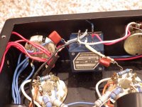
Just FYI, all the pics in this thread are examples I found on the web. My heater wires are twisted tightly but they do follow the same path as the ones in the pictures. They pass between the PS filter section and the line of tubes, alongside a bunch of HT supply wires and across ground circuit wires, and under the right channel output capacitor.
I had thought it was more important to keep them away from input circuitry, but I’ll generally tidy up the amp and see how I can reroute things. Rehoming it in a new chassis with a different layout might be necessary.
What would be a reasonable value for the input bypass capacitor in this amp (pictured between volume pot and input grid below)? There's a 4.7K stopping resistor on the 6SN7 input bypassed by what appears to be a polypropylene film cap.
The rest of the circuit is set for an LF cutoff just below 4Hz. So following that pattern, the input bypass cap could be ~10uF:
159155 / 4700 / 10 = 3.39Hz
I've never seen an input bypass cap before, though, so I'm not sure what common practice might be.
The rest of the circuit is set for an LF cutoff just below 4Hz. So following that pattern, the input bypass cap could be ~10uF:
159155 / 4700 / 10 = 3.39Hz
I've never seen an input bypass cap before, though, so I'm not sure what common practice might be.
Attachments
- Status
- This old topic is closed. If you want to reopen this topic, contact a moderator using the "Report Post" button.
- Home
- Source & Line
- Analog Line Level
- Wright WLA12 / WLA12A Line Stage Topology