In the last 6 months we have been working on a new LDR board for RPI.
While there are a few solutions on the market , we decided to take a look and see how we can improve the LDRs volume attenuator.
The first decision we took is to use 16 bit ADCs and DAC . In our opinion 12 bit is not enough to have a precision thats under 1% for 100k R(highest resistance needed to simulate a pot)
Second decision was to treat the digital side of the board..as analog. So heavily filtered , LDOs everywhere , x7r capacitors.
So board was fired up...and we started to measure the R manually using a precision oscilloscope . First readings showed a 5% difference between target resistance and measured one..
Hmm we scratched our heads and look at whole board. We changed the Mosfet , replace the resistors (better ppm), film capacitors...everything still results were at about 3% dif.
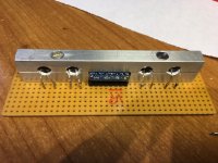
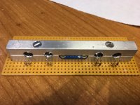
Finally we found out that Cds resistors have a skew depending on temp. So we put both boards inside aluminium casing for thermal inertia we waited 2h before calibrating and then we measured.
DAC in mV ADC in mv Measured Resistance in kilo ohms
Left Channel
673.1294346 1102 100.4
673.0717518 1102 101.1
673.0717518 1101.9375 101.1
673.0717518 1102 101
673.0717518 1102 100.8
673.0717518 1102.125 100.7
673.0717518 1102 100.6
673.0717518 1102 100.4
673.1005932 1102 100.4
673.1005932 1102.125 100.5
673.0717518 1102 100.7
Right Channel
685.8196506 1086.75 100.2
685.8196506 1086.6875 100.8
685.7908092 1086.625 100.8
685.7619678 1086.6875 100.8
685.7619678 1086.6875 100.6
685.7619678 1086.75 100.4
685.7619678 1086.6875 100.2
685.7619678 1086.75 100.1
685.7619678 1086.75 100.2
685.7619678 1086.75 100.4
685.7619678 1086.75 100.5
Maximum skew from target resistance is 1.1%. LR skew is 0.4%
We had a suggestion (thx garry) to use a aluminum casing for LDRs to keep it thermally identical. I suspect that will improve even further the skew.
I believe that we can have an LDR volume attenuator that can compete in precision with 0.1% resistors from 10k to 100k simulated POT
We still have a lot of work on the software side. We want to release it with 10k -100K pot where you can define the number of steps or even program each step independently
While there are a few solutions on the market , we decided to take a look and see how we can improve the LDRs volume attenuator.
The first decision we took is to use 16 bit ADCs and DAC . In our opinion 12 bit is not enough to have a precision thats under 1% for 100k R(highest resistance needed to simulate a pot)
Second decision was to treat the digital side of the board..as analog. So heavily filtered , LDOs everywhere , x7r capacitors.
So board was fired up...and we started to measure the R manually using a precision oscilloscope . First readings showed a 5% difference between target resistance and measured one..
Hmm we scratched our heads and look at whole board. We changed the Mosfet , replace the resistors (better ppm), film capacitors...everything still results were at about 3% dif.
Finally we found out that Cds resistors have a skew depending on temp. So we put both boards inside aluminium casing for thermal inertia we waited 2h before calibrating and then we measured.
DAC in mV ADC in mv Measured Resistance in kilo ohms
Left Channel
673.1294346 1102 100.4
673.0717518 1102 101.1
673.0717518 1101.9375 101.1
673.0717518 1102 101
673.0717518 1102 100.8
673.0717518 1102.125 100.7
673.0717518 1102 100.6
673.0717518 1102 100.4
673.1005932 1102 100.4
673.1005932 1102.125 100.5
673.0717518 1102 100.7
Right Channel
685.8196506 1086.75 100.2
685.8196506 1086.6875 100.8
685.7908092 1086.625 100.8
685.7619678 1086.6875 100.8
685.7619678 1086.6875 100.6
685.7619678 1086.75 100.4
685.7619678 1086.6875 100.2
685.7619678 1086.75 100.1
685.7619678 1086.75 100.2
685.7619678 1086.75 100.4
685.7619678 1086.75 100.5
Maximum skew from target resistance is 1.1%. LR skew is 0.4%
We had a suggestion (thx garry) to use a aluminum casing for LDRs to keep it thermally identical. I suspect that will improve even further the skew.
I believe that we can have an LDR volume attenuator that can compete in precision with 0.1% resistors from 10k to 100k simulated POT
We still have a lot of work on the software side. We want to release it with 10k -100K pot where you can define the number of steps or even program each step independently
Attachments
")
This is meant as a stand alone , rca in/out . WIll work with any single board computer RPI compatible pin outs .
We still have some testing to do, but we expect to have it released before end of April.
We will post the results of our testing on this thread.
Meanwhile please tell us what would you like to see in the software .
We still have some testing to do, but we expect to have it released before end of April.
We will post the results of our testing on this thread.
Meanwhile please tell us what would you like to see in the software .
Aha, now it becomes clear!
Just got external 16bit ADCs fired up on the Ardunio Nano based version. Next step will be the DACs which should be loads better than 8-bit PWM. If you were to use current based dacs then I think you could biff the mosfets and drive the ldrs directly.
Once I have completed the metalwork I'll post some pics of the LDRs thermally coupled.
Once they are coupled you could monitor the temp on the ldrs and compensate on the fly. Another option might be to use a peltier device to maintain a constant temp to the ldrs but that is getting a little silly.
This is meant as a stand alone , rca in/out . WIll work with any single board computer RPI compatible pin outs .
We still have some testing to do, but we expect to have it released before end of April.
We will post the results of our testing on this thread.
Meanwhile please tell us what would you like to see in the software .
Ok, probably a stupid question, but what is the benefit of having a volume control on a seperate Pi? What could be done on the software side exactly?
Shopping list...
I'm sure I'll think of some more
Single ended / balanced option
Option to drive external I2C lO board
Nice display options (OLED)
Selectable impedance
Constant output or input impedance
Selectable number of steps
Calibrated in db
Remote control
Headphone out option
Offsets to allow levelling between different input sources
Remote power control for power amp
Mute out to trigger power amp
Soft mute and power up ramp
I'm sure I'll think of some more
Shopping list...
Single ended / balanced option
Option to drive external I2C lO board
Nice display options (OLED)
Selectable impedance
Constant output or input impedance
Selectable number of steps
Calibrated in db
Remote control
Headphone out option
Offsets to allow levelling between different input sources
Remote power control for power amp
Mute out to trigger power amp
Soft mute and power up ramp
I'm sure I'll think of some more
That answers my question...
Aha, now it becomes clear!
Just got external 16bit ADCs fired up on the Ardunio Nano based version. Next step will be the DACs which should be loads better than 8-bit PWM. If you were to use current based dacs then I think you could biff the mosfets and drive the ldrs directly.
Once I have completed the metalwork I'll post some pics of the LDRs thermally coupled.
Once they are coupled you could monitor the temp on the ldrs and compensate on the fly. Another option might be to use a peltier device to maintain a constant temp to the ldrs but that is getting a little silly.
I don't think its needed. If you calibrate at 22C and use your LDR at 26C , you will get a skew of about 2.5 to 3% (from our internal testing) from calibrated target. However that means that instead of a 10k POT you will have a 10k 300ohm pot and instead of 100k you will have 103k pot.
The important thing is that shunt and series skew is less (and LR skew) , that both move in same direction and keep the attenuation desired and keep the difference between LR at minimum . Then the skew from calibrated becomes meaningless
In our testing skew from Series/Shunt is 0.4% and skew from LR is also 0.4% even at 3% skew overall.
Aha, now it becomes clear!
Just got external 16bit ADCs fired up on the Ardunio Nano based version. Next step will be the DACs which should be loads better than 8-bit PWM. If you were to use current based dacs then I think you could biff the mosfets and drive the ldrs directly.
Once I have completed the metalwork I'll post some pics of the LDRs thermally coupled.
Once they are coupled you could monitor the temp on the ldrs and compensate on the fly. Another option might be to use a peltier device to maintain a constant temp to the ldrs but that is getting a little silly.
Yeap agreed with the rigt DAC you drive the mosfet directly , but pay attention to 2 things. Capacitor for mosfet (characteristics are important) and power has to be very clean..When you talk about 16 bit precision , its important to have no noise.
Funny that is what I have here on the bench with a Arduino Nano. Slooow progress though as my coding skils are not all that.
Regarding LDR temp drift I have found that it is the higher resistances that suffer the most and was wondering it if might be simpler to rule this out by maintaing a constant temp eg: via a small heating resistor?
Regarding LDR temp drift I have found that it is the higher resistances that suffer the most and was wondering it if might be simpler to rule this out by maintaing a constant temp eg: via a small heating resistor?
This is meant as a stand alone , rca in/out . WIll work with any single board computer RPI compatible pin outs .
We still have some testing to do, but we expect to have it released before end of April.
We will post the results of our testing on this thread.
Meanwhile please tell us what would you like to see in the software .
Probably a silly question, but does the LDR board digitize the signal in order to control the volume and then convert it back to analog on the way out or does this just vary the resistance all in the analog domain?
Thanks
Last edited:
Obviously we have not seen anything yet but it would be my assumption that it is a passive LDR based volume control so the only thing in the signal path would be the calibration and maybe a mute relays together with a series and shunt LDR arrangement.
I'm revisiting a similar solution based on a Arduino Nano.
I'm revisiting a similar solution based on a Arduino Nano.
- Status
- This old topic is closed. If you want to reopen this topic, contact a moderator using the "Report Post" button.
- Home
- Source & Line
- Analog Line Level
- New LDR for Rapberry PI