I think I drew that wrong....

I think you did
") I've deleted whatever that was.
I've deleted whatever that was.
I think you did
I hope you didn't that was offensive? It was my crappy way of drawing two toggle switches attached to each other.
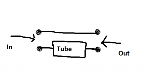
Anyways, here is a more standard drawing that one get people to the second guess what I just drew (hopefully):
What I need is a switch that can both switch the input and output simultaneously, so I don't have to operate two separate switches to do so.
An externally hosted image should be here but it was not working when we last tested it.

Oops. Wrong image url link. One more time:
An externally hosted image should be here but it was not working when we last tested it.
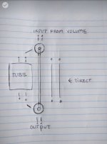
So you want to switch between either 'direct' or to have a 'tube' in the path.
So if you want to switch 'both sides' of each chain then you need a 4 pole switch:
LORLIN - CK1052 - SWITCH, 4 POLE 3 POS | CPC UK
So if you want to switch 'both sides' of each chain then you need a 4 pole switch:
LORLIN - CK1052 - SWITCH, 4 POLE 3 POS | CPC UK
Lets attach whatever that is to the thread:
Thanks. I'm new to posting images. Much appreciated.
So its wired like this. This uses half the switch (two of the four individual switches) and shows just one channel.
To add a photo, files or non standard files.
First click "go advanced" in the box below the "quick reply" message box. Doesn't matter if you decide half way through a message to do that, it carries it forward.
Then click "Manage attachments". Maximise the new Window so that you can see all the text.
Click browse in the first box at the top and find your picture. Repeat for any more pictures.
Click upload... a message appears "uploading"
When complete the files will show as being attached. Now click the small text that says "close this window"
The pictures should now be attached and when you submit your post they will appear.
Make sure your pics aren't too big, a couple of 100k is plenty, and many members object when they are massive and it alters the margins
It tells you in the attachments window what max sizes are allowed.
If you want to attach a file that has a non standard format for example excel, circuit simulation etc then try putting the files in a zipped folder and attaching that.
Thanks. I'm new to posting images. Much appreciated.
To add a photo, files or non standard files.
First click "go advanced" in the box below the "quick reply" message box. Doesn't matter if you decide half way through a message to do that, it carries it forward.
Then click "Manage attachments". Maximise the new Window so that you can see all the text.
Click browse in the first box at the top and find your picture. Repeat for any more pictures.
Click upload... a message appears "uploading"
When complete the files will show as being attached. Now click the small text that says "close this window"
The pictures should now be attached and when you submit your post they will appear.
Make sure your pics aren't too big, a couple of 100k is plenty, and many members object when they are massive and it alters the margins
It tells you in the attachments window what max sizes are allowed.
If you want to attach a file that has a non standard format for example excel, circuit simulation etc then try putting the files in a zipped folder and attaching that.
Attachments
Yep, looks like you want a 4 pole 2 way switch. often written 4PDT, DT meaning dual throw, same as 2 way
Not quite sure how the output integrates into this? Do I reroute the outputs of the tube stage back into the switch?
That's right, you effectively have a switch at both ends like you and Mooly have drawn, think of all 4 switches as completely separate entities
Thanks both of you for the info. I tried to figure out a wiring diagram based on what I have briefly learned about a 4dpdt switch based on what I need to do. I've attached the image (hopefully):
Attachments
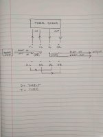
Yep, that's it. I know sometimes it's hard to see the wood for the trees, ha ha, but you've got it. I am intrigued as to what you are planning, a bypassable tube pre amp?
Ha! That's funny
I'm planning on combining an Aikido linestage with either an LDR or AVC. I want the option of choosing active or passive, so I can use it with different amps. I know that it is not good to have too many connections in the signal path, but I'd still like to try.
Do you have a preference either LDR or AVC?
Thanks again for your help! I'm learning.
LDR, Light Dependant Resistor? AVC, (active?automatic?) volume control, no experience with either I'm afraid. Don't get too hung up about connections, so long as it's a good quality switch and the wiring is well screened and not too long it won't make an appreciable difference
- Status
- This old topic is closed. If you want to reopen this topic, contact a moderator using the "Report Post" button.
- Home
- Source & Line
- Analog Line Level
- Type of Switch