does source impedance mean the output impedance of the source?
Yes. Usual values for most circuits are 10k for solid state, and 100k for tubes.
output impedance = 200 ohms.
This is important. Just because a tube stage's small signal output impedance is 200R,
that doesn't mean that it can drive even 1k with low distortion.
The load has to be larger than the open loop Rout to maintain low distortion in the circuit.
Otherwise, the low value load pulls down the open loop gain to the point where
the same feedback resistor values can't work nearly as well as with a high value load.
This can be more easily seen by considering the heavy load as part of the open loop circuit,
where it will reduce the gain and increase the distortion, before the feedback is applied.
The feedback will now be less effective since there is less gain to "throw away", and more
distortion to reduce, than with a light load.
Last edited:
my rule of thumb is to have the lowest pot value that the source can drive *well*. if your source can drive a 1k pot and not get bogged down, then 1k pot it is.
lower values will yield lower noise, usually, but its all about what the source can drive. I don't usually care what the load is, since the load that comes after the pot is usually fairly high-z compared to the circuit's ideal pot value.
lower values will yield lower noise, usually, but its all about what the source can drive. I don't usually care what the load is, since the load that comes after the pot is usually fairly high-z compared to the circuit's ideal pot value.
an attenuator pot for a given circuit??
Depends on the given circuit
") Basically it is a balancing act between lowering distortion (power transfer; impedance matching) and lowering noise. It can be delicate if your whole system is of very high performance (which is why some people try to avoid the pot).
Basically it is a balancing act between lowering distortion (power transfer; impedance matching) and lowering noise. It can be delicate if your whole system is of very high performance (which is why some people try to avoid the pot).Higher pot resistance bring higher noise potential in itself, but it may affect the noise of preceding gain stage. From noise perspective, most of the time we want a low resistance, but low resistance can become a difficult load for the driving stage, hence high distortion.
What is in front of the pot is called the 'source'. It can be a CD/DAC. If the CD/DAC has tube stage, usually it cannot drive low resistance like 10k pot. (The DAC is called to have high output impedance).
It depends on the performance of your whole system, 10k pot can be a problem also even if the DAC is not tube based. Ideally we want a buffer (a high impedance load) between the driving stage and the pot (and also between the pot and preceding stage).
A 10k pot is not suitable to directly 'drive' amplifiers with low input impedance. Ideally you want a buffer stage, or an amplifier with high input impedance, such as an amplifier with JFET input stage.
If buffer is provided only at one end, which one is better, before or after the pot? In most situation (such as most commercial CD players as the source) I prefer after the pot. Most CD players can drive 10k pot with less issues than a 10k pot driving most amplifiers.
Does that answer your question? Of course not. To find the answer I suggest that you read the PDF for the Ovation Symphony preamp by Bonsai at hifisonix.com: Audio Amplifier Design and Music Reviews.
LOL! How did I know you were gonna say that....Depends on the given circuit
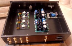
Well, since you've asked... This is the circuit.

As a matter of fact, it IS a buffer... 6922/6DJ8.
More specifically, 2 of them (per stereo channel).
Its part of my new project.
One of those (circuit board) before the attenuator, another board after.
Hence, buffered before AND after the attenuator.
Frankly though, the intent is to use a (cheap) pot temporarily, and eventually sub in a TVC... the real heart of the project.
Firstly because of cost.... the TVCs will cost equal to the whole of the rest of the project.
Nextly because just completing the project will be hard enough (for ME), subbing in the TVC's will be easier later.
It'll also give me the chance to compare the results..
And THAT will be my next line-stage (or whatever the proper term might be)
Selector switch---> buffer-board---> Pot/TVC---> buffer-board---> output terminals (all in a case).


More pix both for the sake of clarity and audio-porn...
As a matter of fact, it IS a buffer... 6922/6DJ8.
More specifically, 2 of them (per stereo channel).
Its part of my new project.
One of those (circuit board) before the attenuator, another board after.
Hence, buffered before AND after the attenuator.
Frankly though, the intent is to use a (cheap) pot temporarily, and eventually sub in a TVC... the real heart of the project.
Firstly because of cost.... the TVCs will cost equal to the whole of the rest of the project.
Nextly because just completing the project will be hard enough (for ME), subbing in the TVC's will be easier later.
It'll also give me the chance to compare the results..
And THAT will be my next line-stage (or whatever the proper term might be)
Selector switch---> buffer-board---> Pot/TVC---> buffer-board---> output terminals (all in a case).
More pix both for the sake of clarity and audio-porn...
Actually it kind of does.....Does that answer your question?
Ok one more pic because of the popular demand (that will hopefully come later)
Project as it sits right now...
Attachments
That circuit is likely to need a regulated power supply. This is because the feedback does not stay the same from audio down to DC, but reduces below about 0.03Hz. Hence any supply rail variations will be amplified by the second triode and sent to the output. Now you can attenuate them at the output (and so avoid woofer flapping) by choosing the right output coupling cap value, but they may still have caused intermodulation in the second stage. A poor design in my view.
source >> vol pot >> receiver has to be considered as two separate connections.AHHhhhhh... now that makes sense!
It is in fact a tube circuit...
(2 actually... POT in between them)
Claimed output impedance = 200 ohms... input obviously much higher as one would expect.. but as I'd mentioned... I'm currently looking into it.
Thanks as always Ray!
analyse the Source >> vol pot
analyse the vol pot >> receiver
for each of those connections you have an output impedance, an input impedance and a pair of wires carrying the one channel of signal.
Aim to have an output impedance:input impedance ratio > 1:5 and going above 1:10 is OK. I aim for 1:20
eg.
source >> vol pot.
200ohms : two wires : 5*200ohms = 1kohms
Use a vol pot that is 1kohms, or higher. 2k and 5k will also work.
I'll choose the 5k to show the second connection.
Vol pot >> receiver.
vol pot output impedance varies from zero ohms to 1/4 of sum of ( vol pot plus source impedance) Rs = 200ohms vol pot = 5000ohms, toatl = 5200ohms.
Vol pot maximum output impedance is 5200/4 = 1300ohms.
1300ohms : two wires : 5*1300ohms = 6500ohms, or higher. 10k 20k 50k and 100k will all work.
Next consider the inadvertant filters due to parasitic and deliberate capacitances.
The 200ohms source can tolerate very high capacitance and not suffer treble roll-off.
F-3dB = 1/2PiRC
maximum tolerable C for a 100kHz roll-off is C<= 1/2PiFR <= 8nF
That's an enormous capacitance to allow 20kHz to pass.
Move onto the 1300ohms maximum output impedance of the 5k vol pot.
Maximum tolerable C for 100kHz roll-off is C<=1.2nF
Still a pretty high allowable capacitance.
But if you chose a 50k vol pot the allowable capacitance drops to <= 127pF
That is just a couple of metres of coaxial cable. There might be an RF filter at the input of the receiver.
Unbuffered vol pots can roll-off the treble if the stack up of impedances and capacitances go too high. Just calculate the numbers to predict what you will end up with.
source >> vol pot >> receiver has to be considered as two separate connections.AHHhhhhh... now that makes sense!
It is in fact a tube circuit...
(2 actually... POT in between them)
Claimed output impedance = 200 ohms... input obviously much higher as one would expect.. but as I'd mentioned... I'm currently looking into it.
Thanks as always Ray!
analyse the Source >> vol pot
analyse the vol pot >> receiver
for each of those connections you have an output impedance, an input impedance and a pair of wires carrying the one channel of signal.
Aim to have an output impedance:input impedance ratio > 1:5 and going above 1:10 is OK. I aim for 1:20
eg.
source >> vol pot.
200ohms : two wires : 5*200ohms = 1kohms
Use a vol pot that is 1kohms, or higher. 2k and 5k will also work.
I'll choose the 5k to show the second connection.
Vol pot >> receiver.
vol pot output impedance varies from zero ohms to 1/4 of sum of ( vol pot plus source impedance) Rs = 200ohms vol pot = 5000ohms, toatl = 5200ohms.
Vol pot maximum output impedance is 5200/4 = 1300ohms.
1300ohms : two wires : 5*1300ohms = 6500ohms, or higher. Receiver input impedance of 10k 20k 50k and 100k will all work.
Next consider the inadvertant filters due to parasitic and deliberate capacitances.
The 200ohms source can tolerate very high capacitance and not suffer treble roll-off.
F-3dB = 1/2PiRC
maximum tolerable C for a 100kHz roll-off is C<= 1/2PiFR <= 8nF
That's an enormous capacitance to allow 20kHz to pass.
Move onto the 1300ohms maximum output impedance of the 5k vol pot.
Maximum tolerable C for 100kHz roll-off is C<=1.2nF
Still a pretty high allowable capacitance.
But if you chose a 50k vol pot the allowable capacitance drops to <= 127pF
That is just a couple of metres of coaxial cable. There might be an RF filter at the input of the receiver.
Unbuffered vol pots can roll-off the treble if the stack up of impedances and capacitances go too high. Just calculate the numbers to predict what you will end up with.
There is one more filter effect to calculate.
Most amplifiers and sources have a coupling capacitor to block DC.
This creates a high pass filter. It can remove your bass signal.
The same formula is used.
Let's assume you have 1uF plastic film capacitor as your DC block in the output of the source and another 1uF at the input of the receiver.
F-3dB = 1/2pi5000ohms*1uF = 31.8Hz @ the 5k vol pot
F-3db = 1/2Pi100kohms*1uF = 1.6Hz @ the 100k receiver.
Cleary the lower input impedance of the vol pot is determining the bass roll-off for this example. Again you analyse what you have to predict your passband.
DF96 has a point. There is DC feedback but no DC connection in the forward path. The first stage is going to try and correct for variations in the second one, completely in vain of course. Do this with circuitry that has higher voltage gain, and it'll latch up at any given opportunity.
Sorry, was a VERY busy week...
Why don't you design (AND IMPLIMENT) a very good alternative?!
I would be DELIGHTED to purchase two boards immediately!!!!
Andrew... that was superb!
Perfectly clear.
I completely understand!
Wish I'd had you as one of my teachers back in school...
In short, its a matter of calculating a bandpass filter with the correct passband, given that (if) you HAVE to have a pot attenuator...
Vis a vis the values you're constrained to work with.
PS: Vendor claims board input impedance = 1M.
I have a dual rail regulated supply for it... +30v / -30v FWIW.That circuit is likely to need a regulated power supply.....
A poor design in my view.
Why don't you design (AND IMPLIMENT) a very good alternative?!
I would be DELIGHTED to purchase two boards immediately!!!!
Andrew... that was superb!
Perfectly clear.
I completely understand!
Wish I'd had you as one of my teachers back in school...
In short, its a matter of calculating a bandpass filter with the correct passband, given that (if) you HAVE to have a pot attenuator...
Vis a vis the values you're constrained to work with.
PS: Vendor claims board input impedance = 1M.
I don't need a buffer.Wikkid said:Why don't you design (AND IMPLIMENT) a very good alternative?!
I would be DELIGHTED to purchase two boards immediately!!!!
If I did need a buffer and decided to use valves I would build a real buffer (i.e. a cathode follower) point-to-point.
If I ever do that I would be happy to share the circuit on the forum.
One thing to consider is that industry standard input impedance for modern equipment is 47K. So if a pot is on the input, you're limited to 47K (or 100K if there's a 100K bleed resistor on the input).
Does this really make a difference? It depends on your drive source. I built a quick and dirty preamp that had an input impedance that varied with volume control setting. I used the "fake log" circuit and in fact the input impedance varied from about 50K to around 9K depending on volume control setting. Of course this is a bad design, but depending on the source this did not always matter. Example - it was entirely inconsequential when driven by my CD player, but actually caused audible bass rolloff at louder volume settings when driven by a tuner via tape out on my receiver.
Cliff notes - stick to industry standard impedances and your device will be universally compatible.
Now I will mention (but not rant* about) what many of you don't want to hear. Buffers (input AND output) really improve the performance of volume controls.
*I had a whole rant written but didn't post it.
Last edited:
I agree........................ Buffers (input AND output) really improve the performance of volume controls.
*I had a whole rant written but didn't post it.
A buffered vol pot is hard to beat.
- Status
- This old topic is closed. If you want to reopen this topic, contact a moderator using the "Report Post" button.
- Home
- Source & Line
- Analog Line Level
- How to determine what value Pot (attenuator)???