Hi everybody
So, finally I'm switching from read-only to write-also mode on diyaudio.com...
I'm working on my first DIY audio project, and could need some help:
I'm piecing together a small, portable Bluetooth amp. I plan to use it sometimes with two, some times with one speaker. When I use it with just one speaker, I would like to be able to throw a switch to sum together the stereo signal coming from the Bluetooth board to a mono signal.
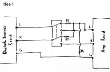
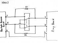
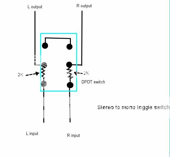
After doing some research on this forum, but also elsewhere (including rane.com) I tried to sketch out two possible solutions (they should be attached to this post). I'm using a DPDT switch in both. In idea 1 the mono signal would be fed to only to the left channel of the amp, thus to the left speaker output. In idea 2 the signal would be fed to both the left and the right channel of the amp.
My 10,000 questions:
Cheers
So, finally I'm switching from read-only to write-also mode on diyaudio.com...
I'm working on my first DIY audio project, and could need some help:
I'm piecing together a small, portable Bluetooth amp. I plan to use it sometimes with two, some times with one speaker. When I use it with just one speaker, I would like to be able to throw a switch to sum together the stereo signal coming from the Bluetooth board to a mono signal.
After doing some research on this forum, but also elsewhere (including rane.com) I tried to sketch out two possible solutions (they should be attached to this post). I'm using a DPDT switch in both. In idea 1 the mono signal would be fed to only to the left channel of the amp, thus to the left speaker output. In idea 2 the signal would be fed to both the left and the right channel of the amp.
My 10,000 questions:
- Do both ideas basically work?
- What kind of resistors should I use?
- In idea 1: Does the mono signal actually have to be connected with a resistor to the ground? That's how I understood the circuits on rane.com.
- In idea 2: If the hot wires have to be connected to the ground with a resistor, where should that happen in this circuit?
Cheers
Attachments
Jon,
thanks a lot for your suggestions.
Do you think it's ok, if I just connect the ground from the Bluetooth device to the amp? Or should the signal, before being fed into the amp, be connected to the ground as suggested in the attached sketch? What difference would that make?
I'm asking because in the stereo-to-mono summing box in the often quoted article «Why Not Wye?» on rane.com the summed signal is connected to the ground with a 20k resistor. In my research I found out that some people do this, some not.
Attachments
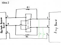
r3 and r4 are closing the dc - path.......etc.
some amplifiers have these built in (at their inputs), some have it not.
if your amp has them not, i would choose 100k or more for r3,r4 ( i presume, r1 and r2 are a few kilo ohm........).
if you don't know, it doesn't hurt if you build them in.
some amplifiers have these built in (at their inputs), some have it not.
if your amp has them not, i would choose 100k or more for r3,r4 ( i presume, r1 and r2 are a few kilo ohm........).
if you don't know, it doesn't hurt if you build them in.
Shielded wires from PCB to switch?
Hi all
I have another question concerning my mono stereo switch:
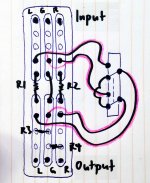
As suggested by JonSnell I will work with idea 2, and I decided to use a small protoboard to assemble everything. The DPDT switch will be mounted on the back panel of my case and connected with short wires to the board (see attached sketch).
My question: Does it make sense to use shielded wires to connect the switch to the board? If so, does it make sense to connect the shield (pink on my sketch) on one end to the ground of the audio signal (which will be accessible on the board), as suggested in my sketch?
Cheers,
Monrin
Hi all
I have another question concerning my mono stereo switch:
As suggested by JonSnell I will work with idea 2, and I decided to use a small protoboard to assemble everything. The DPDT switch will be mounted on the back panel of my case and connected with short wires to the board (see attached sketch).
My question: Does it make sense to use shielded wires to connect the switch to the board? If so, does it make sense to connect the shield (pink on my sketch) on one end to the ground of the audio signal (which will be accessible on the board), as suggested in my sketch?
Cheers,
Monrin
Attachments
Here is a simpler solution.
An externally hosted image should be here but it was not working when we last tested it.
Thanks mjf and Nigel for your suggestions.
Nigel, I thought about using idea 2 from above to have a stereo bypass without any resistors getting in the way, so I won't lose any of the signal strength.
But thinking about that, I assume with 1 or even 10k resistors the loss is probably negligible, no?")
Nigel, I thought about using idea 2 from above to have a stereo bypass without any resistors getting in the way, so I won't lose any of the signal strength.
But thinking about that, I assume with 1 or even 10k resistors the loss is probably negligible, no?
- Status
- This old topic is closed. If you want to reopen this topic, contact a moderator using the "Report Post" button.
- Home
- Source & Line
- Analog Line Level
- Stereo to mono with switch: Do my circuits work?