Does it matter what side of the filter the decoupling cap is? (0.1uf/1M)
If I move it to the left side of the filter couldn't I use low voltage capacitors in the filter instead? I'm trying to make the circuit smaller but still use quality film caps. Say 50v instead of 400v
http://www.beigebag.com/images/riaa/Passive_RIAA_Inverse_Eq_2.gif
Thoughts?
Thanks in advance!
Koda
The RC network on the output the RIAA filter is used to simulate output loading, you need to use the actual values from your own circuit to check the accuracy of the filter. And no where does the voltage rating come into play as shown.
"The .1µF capacitor and the 1M resistor define a -3dB cutoff point of 1.59Hz, which is still far enough away from 10Hz to make no real difference." - Broskie
"The .1µF capacitor and the 1M resistor define a -3dB cutoff point of 1.59Hz, which is still far enough away from 10Hz to make no real difference." - Broskie
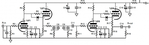
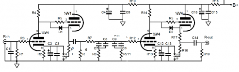
Ok. To clarify Image one is the original Broskie Tetra Phono and the second picture I've moved the coupling cap.
Do you think this filter still work correctly?
I have no spice simulator unless you guys know of a Linux program.
Thanks again.
Do you think this filter still work correctly?
I have no spice simulator unless you guys know of a Linux program.
Thanks again.
Attachments
- Status
- This old topic is closed. If you want to reopen this topic, contact a moderator using the "Report Post" button.