Hey DiyAudio guys! First-time post, but long time lurker ")
Do any of you guys have a good schematic for an NE5532 based tone-control preamp? It's supposed to have at least line-level input and any level of gain between 1x-10x.
Also, I have some issues with another tone control circuit I recently built. The gain on the output is 10 times LESS than what I input. It is significantly quieter and cuts off certain parts of the midrange (for some strange reason)
I know that because I sent the output of this "preamp" into my power amp TPA3118 and noticed a lot of the richness filtered from the music
Here is the schematic:
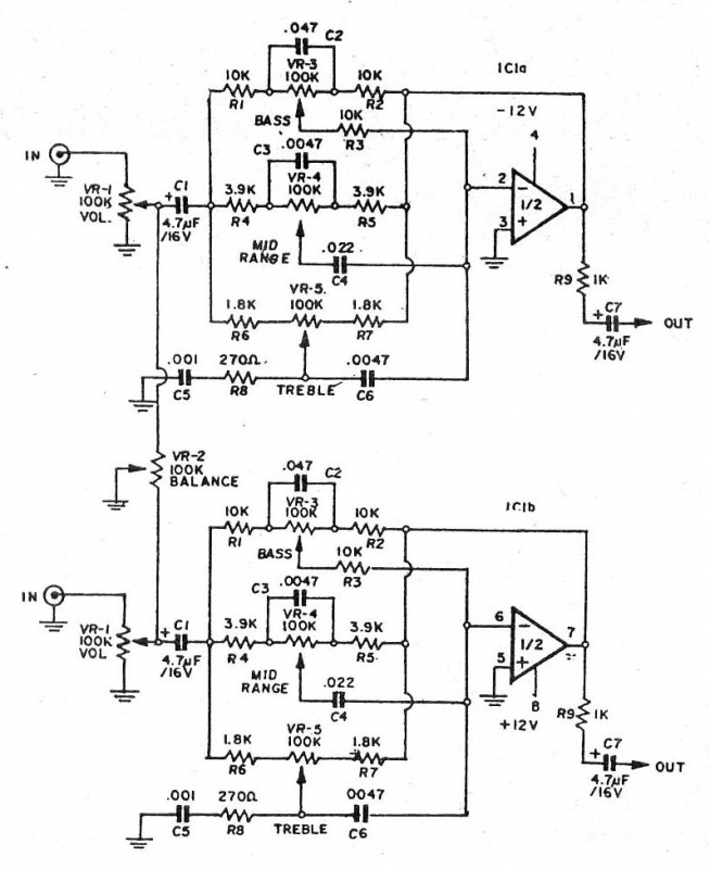
If I set the volume to max on one of the input pots, you can hear music from both channels. However, if I max both L AND R volume pots, there will be distortion and dropping of certain frequencies. (Think of a faint, distorted echo)
Avoiding the problematic volume control, the bass sounds great, the treble control is good but there is just way too many limitations.
IF YOU HAVE ANY ALTERNATIVE SCHEMATICS, and if it's not too much, guide me to the appropriate pages. Thanks!
Do any of you guys have a good schematic for an NE5532 based tone-control preamp? It's supposed to have at least line-level input and any level of gain between 1x-10x.
Also, I have some issues with another tone control circuit I recently built. The gain on the output is 10 times LESS than what I input. It is significantly quieter and cuts off certain parts of the midrange (for some strange reason)
I know that because I sent the output of this "preamp" into my power amp TPA3118 and noticed a lot of the richness filtered from the music
Here is the schematic:
If I set the volume to max on one of the input pots, you can hear music from both channels. However, if I max both L AND R volume pots, there will be distortion and dropping of certain frequencies. (Think of a faint, distorted echo)
Avoiding the problematic volume control, the bass sounds great, the treble control is good but there is just way too many limitations.
IF YOU HAVE ANY ALTERNATIVE SCHEMATICS, and if it's not too much, guide me to the appropriate pages. Thanks!
I have some issues with another tone control circuit I recently built.
Try a 10k volume control in your circuit instead, or (better) an op amp input buffer.
Great Idea, how about
Thanks! I'm going to try that. Also, for some reason and maybe its because of the lack of the buffer, when both knobs are on and I twist one between empty and max, the effect is almost inverse-parabloic. (Plays music at 0, mutes at 50k ohm, plays music again at 100k) is there any explanation to this?
Try a 10k volume control in your circuit instead, or (better) an op amp input buffer.
Thanks! I'm going to try that. Also, for some reason and maybe its because of the lack of the buffer, when both knobs are on and I twist one between empty and max, the effect is almost inverse-parabloic. (Plays music at 0, mutes at 50k ohm, plays music again at 100k) is there any explanation to this?
Thanks! I'm going to try that. Also, for some reason and maybe its because of the lack of the buffer,
when both knobs are on and I twist one between empty and max, the effect is almost inverse-parabloic.
(Plays music at 0, mutes at 50k ohm, plays music again at 100k) is there any explanation to this?
I think this circuit needs a low source impedance to work right, like an op amp buffer, or a 1k pot.
Do you have the balance control connected? Also check the pot wiring.
Last edited:
I ran out of space on my breadboard and decided to use a 51k voltage divider pointing
to ground instead. If the pot balance is that necessary, then I'll have to add it in.
The resistors should be fine instead of the pot, or just remove them completely.
I´d remove both the colume and balance controls and drive tone control straight into C1 Left and C1 Right.
Yes. The circuit needs to be driven directly from op amps at these points. It can be a gain stage or a buffer. You can put the volume control on the input of the buffer or gain stage.
The circuit as shown is poorly thought out and doesn't really work right. Circuits from the web aren't always that good. I didn't scrutinize the rest of the circuit (looks typical) but until you correct this glaring error, you're going nowhere with this circuit.
You can put the volume control and buffer/gainstage together on another board if that works for you.
currently tying to follow this one 3-Way Tone Control it seems to be pretty easy, but im having a hard time finding the 56nf cap! (yes i tried 0.056uF and 56000 pf)
Here is the classic National Semiconductor 3 way tone control circuit. It works.
https://www.google.co.uk/search?q=n...=YvqYWPDpC8GDgAbhto_QCw#imgrc=HCKwTzO_hh0YzM:
https://www.google.co.uk/search?q=n...=YvqYWPDpC8GDgAbhto_QCw#imgrc=HCKwTzO_hh0YzM:
currently tying to follow this one 3-Way Tone Control it seems to be pretty easy, but im having a hard time finding the 56nf cap! (yes i tried 0.056uF and 56000 pf)
http://www.mouser.com/Passive-Compo...apacitors/_/N-9x371?P=1z0wprwZ1z0z7l5Z1yznbzr
http://www.mouser.com/Passive-Components/Capacitors/Film-Capacitors/_/N-9x371?P=1z0wprwZ1z0z819
- Status
- This old topic is closed. If you want to reopen this topic, contact a moderator using the "Report Post" button.
- Home
- Source & Line
- Analog Line Level
- *HELP* NE5532P Tone Control Circuit