It's the first thread in this forum, i.e. Analog Line Level:
http://www.diyaudio.com/forums/anal...osing-potentiometer-passive-preamplifier.html
http://www.diyaudio.com/forums/anal...osing-potentiometer-passive-preamplifier.html
What do you guys think about DACT or the al cheapo version .
http://www.diyaudio.com/forums/parts/241253-guts-tkd-potentiometer-2.html
http://www.diyaudio.com/forums/parts/241253-guts-tkd-potentiometer-2.html
progress
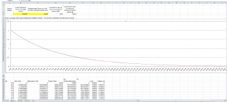
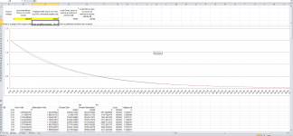
I used the excel sheet provided by Dechrlam. (Thank you!!)")
when I use 10K pot the load impedance seen by the source varies between 9K -10K at maximum and minimum volume respectively, with a smooth plot slope matching close to ideal.
When I go to 20Kpot load impedance seen by the source is between 16K-20K at maximum and minimum volume respectively with slightly more steep plot but still not bad.
Now out put impedance of my source is 560 Ohm and using 2V out.
I am inclined to go with 10K pot as even by general rule it is way above 1:10 rule (560:9000 ,source and pot and 9000:100,000 for pot and amp).Or should I go with 20K? my interconnect capacitance is less than 140pF
Please give me your opinion.
I used the excel sheet provided by Dechrlam. (Thank you!!)
when I use 10K pot the load impedance seen by the source varies between 9K -10K at maximum and minimum volume respectively, with a smooth plot slope matching close to ideal.
When I go to 20Kpot load impedance seen by the source is between 16K-20K at maximum and minimum volume respectively with slightly more steep plot but still not bad.
Now out put impedance of my source is 560 Ohm and using 2V out.
I am inclined to go with 10K pot as even by general rule it is way above 1:10 rule (560:9000 ,source and pot and 9000:100,000 for pot and amp).Or should I go with 20K? my interconnect capacitance is less than 140pF
Please give me your opinion.
Attachments
Last edited:
the source output impedance to receiver input impedance ratio is different for the two vol pot values, 10k & 20k
That's why the range of input impedance is different.
Had you halved the receiver impedance when modelling the 10k vol pot you would have found that the range (as a proportion) of input impedance would have been the same.
In general you need a receiver:source impedance >5:1 and preferably >10:1
A 10k vol pot with a maximum output impedance of 2k5 would suit any Receiver with an input impedance >7k5, but work equally well @ 15k, or even 30k for Zin.
For a 1:20 ratio would require a Receiver Zin of around 50k, or 25k for 1:10
That's why the range of input impedance is different.
Had you halved the receiver impedance when modelling the 10k vol pot you would have found that the range (as a proportion) of input impedance would have been the same.
In general you need a receiver:source impedance >5:1 and preferably >10:1
A 10k vol pot with a maximum output impedance of 2k5 would suit any Receiver with an input impedance >7k5, but work equally well @ 15k, or even 30k for Zin.
you forgot to take account of the vol pot output impedance. Max output impedance is Volpot +Source impedance divided by 4, i.e. {10k+560}/4 = 2640ohmswith 10K pot as even by general rule it is way above 1:10 rule (560:9000 ,source and pot and 9000:100,000 for pot and amp).
For a 1:20 ratio would require a Receiver Zin of around 50k, or 25k for 1:10
Last edited:
Andrew you are saying the calculation using the excel sheet is wrong?
Please explain how did you get the values 2k5 as the maximum out put impedence for a 10K pot.
Also I did not understand how you calculated out impedence vol pot + source output impedence divided by 4?
Please explain how did you get the values 2k5 as the maximum out put impedence for a 10K pot.
Also I did not understand how you calculated out impedence vol pot + source output impedence divided by 4?
Last edited:
No, I did not say the spreadsheet was wrong.
I said
You changed the impedance ratios and thus you changed the range of input impedance.
BTW, a small change in input impedance does not do much if anything to the performance of the Source or the performance of the vol pot.
The only concern may be that the High pass filter or RF attenuation changes a bit and may fall outside some limits you had set for your bass passband or interference rejection.
I said
The ratio of input impedance to source impedance determines the RANGE of input impedance as seen by the source.the source output impedance to receiver input impedance ratio is different for the two vol pot values, 10k & 20k
That's why the range of input impedance is different.
You changed the impedance ratios and thus you changed the range of input impedance.
BTW, a small change in input impedance does not do much if anything to the performance of the Source or the performance of the vol pot.
The only concern may be that the High pass filter or RF attenuation changes a bit and may fall outside some limits you had set for your bass passband or interference rejection.
Just accept that it is true until you find evidence to the contrary. In the meantime you could do some further research into how input attenuation works.I did not understand how you calculated out impedance vol pot + source output impedance divided by 4?
Last edited:
Please explain how did you get the values 2k5 as the maximum out put impedence for a 10K pot.
Kinku, perhaps it's time to learn a little bit of simple maths.
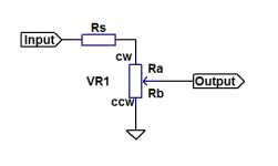
From the attached diagram:
Rs is source resistance, probably 0-100R
VR1 is pot resistance. Ra is upper resistance, Rb is lower resistance (so Ra+Rb=VR1).
From the output, looking leftwards, the source resistance Rt (resistance to ground) is:
Rt = (Rs+Ra)//Rb
Rt = (Rb*(Ra + Rs))/(Ra+Rb+Rs)
This can be thrown into Excel or Calc to explore. As an example, if Rs=100R and VR1=10k:
1) at max volume, Ra=0, Rb=10k and Rt=~99R (not quite 100R as Rs is in parallel with Ra+Rb)
2) at min volume, Rt=0 (as wiper is grounded)
3) Rt(max) occurs when Ra+Rs=Rb, i.e. Ra+Rs/2=Rb, i.e. Ra=4950 and Rb=5050. Rt(max)=2525
If the lead connecting the pot wiper to the load has a capacitance C to ground of 140pF, then a low pass filter is created with a -3dB point Fr(-3dB) of:
Fr(-3dB) = 1/(2*Pi*Rt*C) = ~450kHz
Unless you are entertaining alien bats with a gas discharge tweeter imported from Cygnus A, then this really is nothing to worry about.
Attachments
3) Rt(max) occurs when Ra+Rs=Rb, i.e. Ra+Rs/2=Rb, i.e. Ra=4950 and Rb=5050. Rt(max)=2525.
Slowly picking up, thanks for your patience Ludus .
A bit more explanation here
Could not figure out this part. Why Rs/2?
Could not figure out this part. Why Rs/2?
This is because the max resistance to ground Rt as seen by the load occurs when the two parallel resistances are equal in value. Using the figures from post #31, the combined resistance of Rs and VR1 is 10k + 100 = 10100. Half of this is 5050, i.e. half of VR1 plus half of Rs.
If there are two resistances in parallel, each of 5050, then their combined resistance is 2525. Note that this is the same as Andrew's post above to the effect that the maximum Rt seen by the load equals the pot resistance (10k) plus the source resistance (100) divided by four.
If Rs=0 then Rt simply becomes (VR1/2) // (VR1/2) ("//" means in parallel with). Rt now equals 2500.
It might be conceptually easier to lump Rs and VR1 together, so if Rs=100 and VR1=10k, look at them as a 10100 ohm potentiometer. Once again, Rt = (10100/2) // (10100/2) = 2525.
As you move the wiper away from the arithmetric mid-point, so that the two parallel resistances are not equal, Rs decreases. For example, if Rs+Ra=5080 then Rb=5020 and Rt=2524.91, less than the maximum of 2525.
I hope this clarifies things!
Kinku, perhaps it's time to learn a little bit of simple maths.
From the attached diagram:
Rs is source resistance, probably 0-100R
VR1 is pot resistance. Ra is upper resistance, Rb is lower resistance (so Ra+Rb=VR1).
From the output, looking leftwards, the source resistance Rt (resistance to ground) is:
Rt = (Rs+Ra)//Rb
Rt = (Rb*(Ra + Rs))/(Ra+Rb+Rs)
This can be thrown into Excel or Calc to explore. As an example, if Rs=100R and VR1=10k:
1) at max volume, Ra=0, Rb=10k and Rt=~99R (not quite 100R as Rs is in parallel with Ra+Rb)
2) at min volume, Rt=0 (as wiper is grounded)
3) Rt(max) occurs when Ra+Rs=Rb, i.e. Ra+Rs/2=Rb, i.e. Ra=4950 and Rb=5050. Rt(max)=2525
If the lead connecting the pot wiper to the load has a capacitance C to ground of 140pF, then a low pass filter is created with a -3dB point Fr(-3dB) of:
Fr(-3dB) = 1/(2*Pi*Rt*C) = ~450kHz
Unless you are entertaining alien bats with a gas discharge tweeter imported from Cygnus A, then this really is nothing to worry about.
Thanks Ludus, This is helpful. I'm working on a passive 'loudness' filter.
-
Really helpful, Ludus 
While we're at it, can you (or anyone else) please explain the reasoning behind a particular potentiometer value being recommended for a buffer or preamp? I had asked this before on another thread and AndrewT had helpfully recommended a 10K log which I have been dutifully using (on Keantoken's Kuartlotron buffer), without really understanding why. Also I haven't grasped the parts about driving a certain capacitance load or length of interconnect cable.
Thanks in advance.
Really helpful, Ludus
While we're at it, can you (or anyone else) please explain the reasoning behind a particular potentiometer value being recommended for a buffer or preamp? I had asked this before on another thread and AndrewT had helpfully recommended a 10K log which I have been dutifully using (on Keantoken's Kuartlotron buffer), without really understanding why. Also I haven't grasped the parts about driving a certain capacitance load or length of interconnect cable.
Thanks in advance.
Speaking for my purposes, the power amp target is a class-d chip amp. Hi z volume pot can be trouble in the chip input-feedback junction. And also more susceptible to coupled noise.
Alps 10k is highest value volume pot i use. 5k is better but not available from all suppliers .
Alpha Tiawan 10k i like along with Alps.
-
please explain the reasoning behind a particular potentiometer value being recommended for a buffer or preamp?
I haven't grasped the parts about driving a certain capacitance load or length of interconnect cable.
As an arbitrary choice, let's say we want to avoid a loss of more than 2dB from loading effects.
Then the pot should be more than 4 times the source resistance.
And also then it should be less than 1.25 times the load resistance.
If these two limits leave a range of possible pot values in between,
then choose further based on whether there is much input capacitance in the load,
and if so then you would choose the smallest pot within the range, to minimize the hf rolloff.
All cable has a certain amount of capacitance per foot, and all amplifiers have a certain amount
of capacitance at their inputs. These can work with the volume control resistance to reduce the hf bandwidth.
The volume control presents a maximum resistance to the load of 1/4 its value. For example,
if you have a 10k control the load sees at most 2.5k, which happens at the -6dB or half resistance
point of rotation. Then the hf rolloff would be at 1/ [2 Pi x 2.5k x Cinput ] for a 10k pot.
A similar situation can roll off the bass due to too small resistance loading on the source component,
if there is an output coupling capacitor in the source. Then you would have a bass rolloff of about
1/ [2Pi x Rpot x C coupling] at typical pot settings.
Last edited:
Really helpful, Ludus
While we're at it, can you (or anyone else) please explain the reasoning behind a particular potentiometer value being recommended for a buffer or preamp? I had asked this before on another thread and AndrewT had helpfully recommended a 10K log which I have been dutifully using (on Keantoken's Kuartlotron buffer), without really understanding why. Also I haven't grasped the parts about driving a certain capacitance load or length of interconnect cable.
Thanks in advance.
If you go to DACT website they have small excell sheet where you can type in various potentiometer values and see what it does with attenuating frequency responses at each level. The capacitance of some reasonableRCA cables usually around 100pF-140pF( eg monoprice brand for 3 feet)
Also the sticky thread at the beginning of this forum explains with the help of an excell sheet why 10K works for most applications. At the end I think the max input impedence you can see in amps is 100K or much lower like the OP give as an example 3.2K.
http://www.diyaudio.com/forums/anal...osing-potentiometer-passive-preamplifier.html
Last edited:
- Status
- This old topic is closed. If you want to reopen this topic, contact a moderator using the "Report Post" button.
- Home
- Source & Line
- Analog Line Level
- Simplest Passive Preamp design