Can someone advice low noise and high-gain Pre-amplifier for Electret Microphone,
maybe with transistors, that amplifies the output signal of an electret capsule
microphone to audio line levels. Power supply voltage 12V.
This is for 9V, but it can easily be adapted for 12V.
http://www.ti.com/lit/ug/tidu765/tidu765.pdf
Search inside DIYAudio itself, no need to go far.
If a Pro electret microphone, output is compatible with Pro dynamic mics, so any such preamp will fit yours.
If it´s a hobbyist "electret capsule with a 2k to 10k resistor connected to a 1.5 to 9V battery, it´s even easier.
Since it´s unbalanced and relatively high level, any simple preamp with gain 20X to 50X will do.
Something like this should work well. I'd use a slightly more modern opamp than TL071 though (which is not too great at low supplies and has fairly low GBW and poor output drive) - maybe a trusty NE5534 or OPA132/134, with a 10k log pot, 220R R1 and 220µ C3, and like 100 nF of decoupling capacitance from V+ to V- at the part.
Maximum gain like this is ~33 dB. With an electret you can use 50+ dB in some cases, so you may want to use a pot as high as 100k.
Note that the (cheap, plentiful and well-performing) NE5534 has a minimum stable gain of 3, so it would be advisable to insert 390-470R in series with the pot. You can add extra compensation capacitance to make it unity gain stable, but this reduces performance at the high gains you normally want in an amplifier like this.
You won't ever need anything with lower voltage noise than these parts. Noise of the capsule itself will already totally swamp it. Depending on capsule, source impedance could be several kOhms, so you actually don't want too much current noise, which tends to be inversely proportional to voltage noise. Again, NE5534 is rated at 0.6 pA/sqrt(Hz), no problems expected beyond 10 kOhms here.
Quite arguably, the effort put into cleaning up electret capsule bias voltage plays a bigger role than noise performance of the actual amplifier. (Fun fact: Bias voltage of onboard audio tends to be more or less terribly noisy.) If you want to get fancy, you could install something bigger than the 47 µF filter capacitor, or go from a 1st-order RC to a 2nd-order one (with 470R+470R).
Something like this should be installed in a grounded metal case. Make sure you use insulated jacks where needed to avoid introducing ground loops.
Regular electret microphone capsule, omnidirectional. Which pick up the sound of an audio source and amplify it to audio line levels. Probably around 100 mV or so.
It's important that microphone need have a good low frequency response, to prevent picking up echo sounds.
Yes, I considered this TI pre-amp, but not sure how to proprerly adjust it for 12V.
It's important that microphone need have a good low frequency response, to prevent picking up echo sounds.
This is for 9V, but it can easily be adapted for 12V.
http://www.ti.com/lit/ug/tidu765/tidu765.pdf
Yes, I considered this TI pre-amp, but not sure how to proprerly adjust it for 12V.
An externally hosted image should be here but it was not working when we last tested it.
Regular electret microphone capsule, omnidirectional. Which pick up the sound of an audio source and amplify it to audio line levels. Probably around 100 mV or so.
It's important that microphone need have a good low frequency response, to prevent picking up echo sounds.
Yes, I considered this TI pre-amp, but not sure how to proprerly adjust it for 12V.
An externally hosted image should be here but it was not working when we last tested it.
I authored that document. I recommend reading through the entire document so you understand why each component value was chosen. Then you will understand how to modify it for your particular use.
As-is it will work fine for most capsules with a 12V supply. If you want, you can recalculate R1 to achieve the desired voltage drop across the capsule.
I have read that doc. If use this electret mic, and power supply 12V: I calculated R1 and C3 values based on (9) and (11) formulas respectively, and got R1 = 21kΩ and C3 = 1.51uF (microFarads). Is that correct?
But not sure, what will be the output voltage of the op amp with this components? Is the output voltage enough to drive LM324 op amp?
Is the OPA172 better than TL071 for this application?
Last edited:
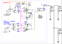
I want make pre-amplifier part for analog electronic circuit (color organ). Audio can enter the circuit in two ways: either thru the electret mic, or thru Line-in jack. The audio from two different audio sources (electret mic and Line-in) need be amplified before being fed to four separate filter circuits and processing it with band-pass filters.
The example below show pre-amps built on LM324, I want replace it with OPA2172 op-amp. Need help to construct this correctly, your advices and suggestions are welcome.
The example below show pre-amps built on LM324, I want replace it with OPA2172 op-amp. Need help to construct this correctly, your advices and suggestions are welcome.
An externally hosted image should be here but it was not working when we last tested it.
The OPA opamp should be OK as it is specified down to <5 volts supply voltage. Feeding 2.5 volts DC into each pot (which is what the circuit will do) is bad design, they should be AC coupled. Having a pot (or preset) in the feedback loop is not optimal for gain control but it does have the advantage of simplicity. If you use a pot then it needs to be well shielded with the body grounded to avoid pickup.
The line inputs have a very low input impedance of 1k, and a pretty high LF roll off point with just a 4.7uf coupling cap.
The mic input is low impedance too. Can an electret drive 1k ? Both inputs are inverting of overall phase.
It is what it is... a workable but pretty generic type of circuit. It is simple and easy to build though.
Hi, the LM324 would be fine as it doesn't need to be HiFi for this aplication. But if you want to use the OPA2172 ok.
I think at least a 9V power supply would be better, with the 100uf cap too. You only need one half supply to feed both OpAmp + inputs, as i've shown.
Note that C1/5/6 polarity are reversed, & i've added a 4.7uf to the output. R2/6/7 changed to 10k.
You should then be good to go")
I think at least a 9V power supply would be better, with the 100uf cap too. You only need one half supply to feed both OpAmp + inputs, as i've shown.
Note that C1/5/6 polarity are reversed, & i've added a 4.7uf to the output. R2/6/7 changed to 10k.
You should then be good to go
Attachments
Hi, thanks for the advice.Hi, the LM324 would be fine as it doesn't need to be HiFi for this aplication. But if you want to use the OPA2172 ok.
I think at least a 9V power supply would be better, with the 100uf cap too. You only need one half supply to feed both OpAmp + inputs, as i've shown.
Note that C1/5/6 polarity are reversed, & i've added a 4.7uf to the output. R2/6/7 changed to 10k.
You should then be good to go
LM324 would be OK, but its quad channel op-amp, though. It would be preferable double channel version. Power supply for all circuit is +12V.
For microphone input main trouble is that capsule microphones don't have a good low frequency response and they can also pick up echo sounds.
@ kvazar
When i posted Moolys post wasn't there ? He makes some good points, which are included anyway in my post.
Use any decent dual OpAmp you like on 12V. You should have said it was going to be 12V & not 5V !
A capsule microphone should be fine for your purpose. Or just use the line input.
When i posted Moolys post wasn't there ? He makes some good points, which are included anyway in my post.
Use any decent dual OpAmp you like on 12V. You should have said it was going to be 12V & not 5V !
A capsule microphone should be fine for your purpose. Or just use the line input.
Well, how this design can be improved, from your point of view ?The OPA opamp should be OK as it is specified down to <5 volts supply voltage. Feeding 2.5 volts DC into each pot (which is what the circuit will do) is bad design, they should be AC coupled. Having a pot (or preset) in the feedback loop is not optimal for gain control but it does have the advantage of simplicity. If you use a pot then it needs to be well shielded with the body grounded to avoid pickup.
An externally hosted image should be here but it was not working when we last tested it.
Looking at the full circuit and seeing what it all does...... well I don't think much in the way of changes are needed. The use of an OPA opamp is not really called for because the final output is an incandescent lamp. So noise/distortion/slew rate, non of it really matters now.
The changes that were mentioned to raise the input impedance are still worthwhile though. I can't see the FET type mentioned anywhere but something like the 2N7000 type of device looks suitable.
The changes that were mentioned to raise the input impedance are still worthwhile though. I can't see the FET type mentioned anywhere but something like the 2N7000 type of device looks suitable.
- Status
- This old topic is closed. If you want to reopen this topic, contact a moderator using the "Report Post" button.
- Home
- Source & Line
- Analog Line Level
- Pre-amplifier for electret mic and Line-in audio sources