I'm working on an application for which I would like to continually measure the DC resistance across a "sense" resistor in series with a loudspeaker driver. This will be connected to an amplifier with a fixed DC output voltage (established by a servo circuit).
The DC voltage produced by the amplifier will be on the order of 50mV. The sense resistor is on the order of 50-100 times smaller than the voice coil DC resistance. This means that the DC voltage across the sense resistor is about 0.5-1 mV. Along with this small DC signal, there will be a LARGE AC signal from the amplifier. Let's say it is 80Vpk-pk, because it will be. It could even be more. And this could be at frequencies as low as 10-20Hz because this is a subwoofer. As a result, I need quite a lot of filtering to remove the AC components so that what is remains is the small DC signal, and I want to amplify this so that my measuring equipment has a signal that is on the order of a few VOLTS, so that is 1,000x-10,000x amplification.
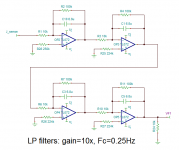
I took a stab at this using a 4-stages of first order filter plus gain (see attached circuit). I have been simulating this circuit in TINA. I chose the TL072 because it's a JFET input part, so relatively low input bias current, etc. Each stage has 10x gain and has a corner frequency of 0.25 Hz. Although this is a relatively low order filter, because the corner frequency is quite low the AC component seems to be sufficiently filtered out. Also, I am able to add a large resistance in series with to the non-inverting terminal to trim offset down to pretty much zero (to uV levels) at the output, even with all that gain. As the voice coil resistance changes, there are changes on the order of a volt per Ohm of change in the VC. That is easily measurable. By knowing the sense resistor resistance, and the DC voltage I can back calculate Re. Now that would be interesting.
I know the dark side of simulations, and there are probably lots of things that could go wrong with this kind of circuit that my nice linear sim does not show. I am very concerned about the trimming of the DC offset. Since the output is nominally at a couple of volts, if the DC level at the output drifts a few mV that won't matter. But with the HUGE amount of gain used I am worried that thermal drifts in the resistance values and amplifier properties might really screw things up. The problem is that I am not familiar how to guesstimate these effects.
The TL072 has a thermal drift in the offset voltage of 18 uV/C. If the gain is 10,000x, this seems to mean the the output might drift by 18mV per degree C, so if the part heats from 20C to 50C the total drift would be around 0.5V. That's too much. I found a couple of low-drift JFET devices I could simulate that have about 10x lower thermal drift. The problem was that I could no longer effectively trim out the DC offsets that I would get, like I can with the TL072. I did not try to apply a voltage bias to the non-inverting input, or any other techniques, only to play with the resistance on that terminal. So perhaps I should consider some other approaches.
I am looking for input on how to come up with a robust circuit for this application, whether it is to use the one I show below with the TL072, substitute another op-amp, or perhaps do something different alltogether.
The DC voltage produced by the amplifier will be on the order of 50mV. The sense resistor is on the order of 50-100 times smaller than the voice coil DC resistance. This means that the DC voltage across the sense resistor is about 0.5-1 mV. Along with this small DC signal, there will be a LARGE AC signal from the amplifier. Let's say it is 80Vpk-pk, because it will be. It could even be more. And this could be at frequencies as low as 10-20Hz because this is a subwoofer. As a result, I need quite a lot of filtering to remove the AC components so that what is remains is the small DC signal, and I want to amplify this so that my measuring equipment has a signal that is on the order of a few VOLTS, so that is 1,000x-10,000x amplification.
I took a stab at this using a 4-stages of first order filter plus gain (see attached circuit). I have been simulating this circuit in TINA. I chose the TL072 because it's a JFET input part, so relatively low input bias current, etc. Each stage has 10x gain and has a corner frequency of 0.25 Hz. Although this is a relatively low order filter, because the corner frequency is quite low the AC component seems to be sufficiently filtered out. Also, I am able to add a large resistance in series with to the non-inverting terminal to trim offset down to pretty much zero (to uV levels) at the output, even with all that gain. As the voice coil resistance changes, there are changes on the order of a volt per Ohm of change in the VC. That is easily measurable. By knowing the sense resistor resistance, and the DC voltage I can back calculate Re. Now that would be interesting.
I know the dark side of simulations, and there are probably lots of things that could go wrong with this kind of circuit that my nice linear sim does not show. I am very concerned about the trimming of the DC offset. Since the output is nominally at a couple of volts, if the DC level at the output drifts a few mV that won't matter. But with the HUGE amount of gain used I am worried that thermal drifts in the resistance values and amplifier properties might really screw things up. The problem is that I am not familiar how to guesstimate these effects.
The TL072 has a thermal drift in the offset voltage of 18 uV/C. If the gain is 10,000x, this seems to mean the the output might drift by 18mV per degree C, so if the part heats from 20C to 50C the total drift would be around 0.5V. That's too much. I found a couple of low-drift JFET devices I could simulate that have about 10x lower thermal drift. The problem was that I could no longer effectively trim out the DC offsets that I would get, like I can with the TL072. I did not try to apply a voltage bias to the non-inverting input, or any other techniques, only to play with the resistance on that terminal. So perhaps I should consider some other approaches.
I am looking for input on how to come up with a robust circuit for this application, whether it is to use the one I show below with the TL072, substitute another op-amp, or perhaps do something different alltogether.
Attachments
Personally I would use a differential amplifier on the front end to keep noise down at those signal levels.
OK, but what are you connecting those differential inputs to? One is ground...
Edit: OK now I understand. This is to eliminate the effect of parasitic resistances between the shunt and ground.
Last edited:
OK, but what are you connecting those differential inputs to? One is ground...
Either side of the sense resistor as close to the pins as possible.
What is the end application and what are you trying to accomplish?
The large AC amplitude superimposed on a minute DC voltage which is the target value you are trying to sense is challenging.
Normally you might start with a sense resistor with kelvin connections and an INA, this would eliminate the errors due to IR drop between your sense resistor and the measurement ground. The problem is you have a huge amount of AC you are not interested in and a very small DC value you are. Very draconian filtering in front of an INA would be required which also would have little dynamic range due to the residual AC present meaning that relatively little gain could be used in that stage.
There are op-amps with much lower offsets (in the uV range) that do not need to be trimmed. Trimming at these gains and voltages is going to be a short term stable proposition at best. Linear, Analog Devices and TI all make suitable op-amps.
I would use 2nd or 3rd order VCVS filters, possibly implemented with gain instead of a multitude of low gain 1st order filters.
There are other possibilities using integrators for example in the sense loop that might work better if the application were known.
you are pretty much guaranteed that the low passed DC measurement will be pretty useless for improving any Audio property of the woofer - its AC Audio frequency R will be being modulated by the temperature swings of voice coil and its largish tempco for any conductor you would want to use
there are other current sense techs - Hall/GMR can measure DC mag field near a current carrying wire and you can add a mag field concentrator structure
there are other current sense techs - Hall/GMR can measure DC mag field near a current carrying wire and you can add a mag field concentrator structure
you are pretty much guaranteed that the low passed DC measurement will be pretty useless for improving any Audio property of the woofer - its AC Audio frequency R will be being modulated by the temperature swings of voice coil and its largish tempco for any conductor you would want to use
Haha, that is actually the application: measuring the change in VC resistance versus time. I'm only interested in measuring the VC resistance. Since this is a subwoofer application the thermal mass is not insignificant, so the the time constant is on the order of 10-20 seconds or more. Thus heavy filtering with Fc 0.25Hz is OK.
1 mV input with gain of 10,000X means your first stage needs input offset voltage less than 100 nanovolts. Unfortunately nobody sells anything with input voltage offset that low.
OK, I see the futility. I can use much lower gain actually. I just bought a 16-bit ADC that can operate at as low as 250mV full scale. If I use a slightly larger sense resistor I can probably live with a Dc gain in the range of 100x-1000x.
At this point I am sensing that I need to:
use a differential stage across the sense resistor
use a low-drift, low-offset amplifier
use a higher order filter per amplifier and fewer amplifiers overall.
Is that going in the right direction?
This has all been done before, actually, just in a slightly different way. See here:
Hot Stuff: Loudspeaker Voice-Coil Temperatures Making The Measurements | Stereophile.com
Instead of using a current source, I will force the amplifier to have a fixed DC offset of 50mV.
I was hoping that I could use a bunch of gain to bring up the signal level to around 1V to make use of the full scale of my ADC. But it seems that if DC accuracy is very important (which it is) I will be fighting DC offsets and drift no matter what. The key question is how to minimize these problems and so far the responses have been helpful in this regard.
If you want to see a small change in a large value, look for some kind of bridge.
The one below balances the hot VC against a stable resistor. When the 60r:1 balances the "6r":0.1, output is zero. As the "6r" changes value, the output rises.
You still need the DC and a heavy high-cut, because we know the "6r" will be 30+r at 40Hz and rising above 12r by 1KHz or less.
The "fixed" Rs should have low tempco, but not lab-grade because we suspect the woofer impedance varies very widely with high power.
This will incidentally tell you thermal DE-compression, as when you put your woofer outside in Maine. (DCR drops, coil sucks more power.)
Attachments
With a dual voice-coil woofer in a proper setup most of the AC is cancelled out while the DC voltage doubles. This makes the filter constraints much more relaxed.
Also test current can be made higher as it does not offset rest position, increasing S/N.
It's then quite shocking to learn/see that the VC heating is very immediate (adiabatic), no time constant involved. The only time constant we see is the time to reach thermal equilibrium. Just like what you see when you charge a capacitor through a resistor, the voltage rise starts immediately and continues with the same slope until it finally starts to top out after some time.
This was actually my first idea. In another thread in this forum a member suggested the bridge arrangement but connected to an integrator. Evidently Birt used this to modulate the output impedance of an amplifier.If you want to see a small change in a large value, look for some kind of bridge.
The one below balances the hot VC against a stable resistor. When the 60r:1 balances the "6r":0.1, output is zero. As the "6r" changes value, the output rises.
You still need the DC and a heavy high-cut, because we know the "6r" will be 30+r at 40Hz and rising above 12r by 1KHz or less.
The "fixed" Rs should have low tempco, but not lab-grade because we suspect the woofer impedance varies very widely with high power.
This will incidentally tell you thermal DE-compression, as when you put your woofer outside in Maine. (DCR drops, coil sucks more power.)
Now that I have paid more attention to which amplifier (op-amp) type to use, I have returned to this idea and it seems to be workable, better than trying to measure only the DC across the sense resistor. Even with a precision op-amp with low offset voltage and drift, the integrator needs to be trimmed using an additional resistor on one of the inputs. But since there is no gain used, the errors will likely be less severe overall. The integrator output can be monitored over time. The output will continue to climb when the bridge is unbalanced (when the VC heats up) and at some point it must be reset to remain within rail voltages and within the measurement range of my ADC.
In my sim the sensitivity is pretty good as long as I can keep the bridge in balance with the VC cold. I was not sure I could do that, and that was one reason why I was investigating the filtering with high gain approach. This will need some special care, because once the system is going and VC hot you cannot tell if the bridge arrangement has drifted, for instance because the sense resistor has heated up a little itself and its resistance changed slightly. The bridge arrangement is much more sensitive to this kind of error.
Haha, that is actually the application: measuring the change in VC resistance versus time. I'm only interested in measuring the VC resistance. Since this is a subwoofer application the thermal mass is not insignificant, so the the time constant is on the order of 10-20 seconds or more. Thus heavy filtering with Fc 0.25Hz is OK.
Ok, so you want to measure the VC resistance,probably as a temperature indicator or to measure power compression.
Fine.
Buy why are you obsessed with measuring possible resistance change in the 0.1 ohm sensing resistor?
I'm not. I'm measuring the voltage across the sense resistor. This is in series with the loudspeaker. At DC there is only the VC resistance in series with the sense resistor - it's a voltage divider. If you impose a DC voltage across this voltage divider and one of the resistances changes, the voltage drop across each of the resistors will change and by measuring one of the resistances and give the DC voltage imposed you can calculate the other resistance. The assumption is that the resistance of the sense resistor will NOT change!Ok, so you want to measure the VC resistance,probably as a temperature indicator or to measure power compression.
Fine.
Buy why are you obsessed with measuring possible resistance change in the 0.1 ohm sensing resistor?
- Status
- This old topic is closed. If you want to reopen this topic, contact a moderator using the "Report Post" button.
- Home
- Source & Line
- Analog Line Level
- how to design very stable, DC accurate LP filter with lots of gain?