Thanks for that Geoff.
It would be interesting to view your Preamplifier?
Rear & Front panels and the wiring?
http://www.diyaudio.com/forums/attachment.php?attachmentid=643372&stc=1&d=1509559583
http://www.diyaudio.com/forums/attachment.php?attachmentid=643373&stc=1&d=1509559583
http://www.diyaudio.com/forums/attachment.php?attachmentid=643374&stc=1&d=1509559583
http://www.diyaudio.com/forums/attachment.php?attachmentid=643375&stc=1&d=1509559583
Attachments
Great finish Geoff! Looks superb!
A few questions if you don't mind.
What case did you use?
What Mains power switch did you use?
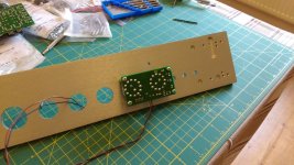
How did you manage to drill the holes for the Rear Panel pcb's?
What monster do you have underneath the Preamp?
Any advise on the construction, wiring etc?
Thanks
A few questions if you don't mind.
What case did you use?
What Mains power switch did you use?
How did you manage to drill the holes for the Rear Panel pcb's?
What monster do you have underneath the Preamp?
Any advise on the construction, wiring etc?
Thanks
Last edited:
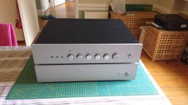
It's the HiFi2000 Slimline 2U. It could easily have gone into something smaller but I wanted it to match the 100W power amp I was building at the same time.Great finish Geoff! Looks superb!
A few questions if you don't mind.
What case did you use?
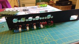
The front panel mains power switch is a Schurter MSM L19 2 pole single throw illuminated switch (Farnell o/n 1637578)What Mains power switch did you use?
All the rear panel holes were done for me on a Water jet machine. The through holes (for knobs, switches and LED) were also cut on the waterjet machine. I had to drill the blind holes for mounting the front panel switch pcb on a pillar drill (thank you to my next door neighbour for use of it) and hand tapped them to suit M3 mounting posts.How did you manage to drill the holes for the Rear Panel pcb's?
I drew the panels up with a CAD package. I used LibreCAD 2D software at first, then switched to FreeCAD 3D software as my waterjet guy mentioned that most CNC machine shops prefer to receive 3D drawing. As a starting point for the panels, HiFi2000 have the case drawings available on their website.
It's a 100W class B (Doug Self Load-Invariant design).What monster do you have underneath the Preamp?
I chose an Modushop by Hi-Fi 2000 | Contenitori per Elettronica | Electronic Enclosures | Hi Fi Chassis all black Dissipante case for the Elektor Q-Watt i built. 145W - 8 Ohms / 220W - 4Ohms. Great quality cases!
For the Elektor Preamplifier 2012 i down scaled the case and chose an RS | PF-19 Ventilated Rackmount Enclosure with Handles, 2U, 84 HP, 245mm Deep |
I recently took my case to a company to get it Water Jet Drilled. They are currently working on their AutoCad program and will advise next week.
Any advise you can pass on about the wiring and construction?
geoffw1, can you give any advise on how you hope to label your front and rear panels?
My case is black http://uk.rs-online.com/web/p/rackmount-enclosures/6657719/?searchTerm=665-7719&relevancy-data=636F3D3126696E3D4931384E525353746F636B4E756D626572266C753D656E266D6D3D6D61746368616C6C26706D3D5E285C647B362C377D5B4161426250705D297C285C647B337D5B5C732D2F255C2E2C5D5C647B332C347D5B4161426250705D3F292426706F3D3126736E3D592673743D52535F53544F434B5F4E554D4245522677633D4E4F4E45267573743D3636352D37373139267374613D3636353737313926
Not too sure how i can do mine.
I used water slide transfers to do the labelling of the back panel. I tried this on a reject piece of front panel material but I (and especially the wife) wasn't happy with the results so I haven't labelled the front panel at all. It's not really a problem as once everything is set up to match power amp / speaker / room, the only controls being adjusted are volume (it has a larger diameter knob than rest) and the source select rotary switch.geoffw1, can you give any advise on how you hope to label your front and rear panels?
My case is black | PF-19 Ventilated Rackmount Enclosure with Handles, 2U, 84 HP, 245mm Deep |
Not too sure how i can do mine.
If I was doing the panels again, I would get them engraved or laser printed at the same time as being CNC drilled.
I have finally been able to get back to this project build after so long.
Can anyone please give me any advise and steps that i should take and be aware of when doing the wiring?
Are there straight forward guides available of all the connections, including the d.c. connections?
With thanks
Calpe
Can anyone please give me any advise and steps that i should take and be aware of when doing the wiring?
Are there straight forward guides available of all the connections, including the d.c. connections?
With thanks
Calpe
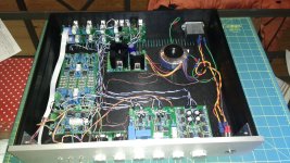
Wiring list is attached. Lengths and colours are what suited my case /internal board positioning.Can anyone please give me any advise and steps that i should take and be aware of when doing the wiring?
Are there straight forward guides available of all the connections, including the d.c. connections?
With thanks
Calpe
Wire size, headers, crimps I used are detailed in previous posts (#35 - 39, if I remember correctly).
View attachment Interconnect.pdf
Thanks Geoff.
Just to mention to the late builders (like me) the NE5532's that were available when i purchased them were the NE5532AP.
http://uk.farnell.com/texas-instruments/ne5532ap/op-amp-dual-low-noise-5532-dip8/dp/1106091?ost=NE5532AP&ddkey=http%3Aen-GB%2FElement14_United_Kingdom%2Fsearch
You'll see here the supply voltage range is +5v - 15v.
The Elektor project has 17v supplies from the PSU.
In the above technical sheet for this i.c. it shows max. voltage is 22v, but recommended supply is 15v.
I wrote to Elektor explaining this and they told me to play it safe reduce R2 & R4 from 1.3k to 1.1k, which i have done, reducing the PSU o/p from 17 to 15v.
As stated by various other people in this post, +/-17V is absolutely fine for the NE5532,ME5534, LM4562 devices used in this design. It is well within the rated voltages for the devices.Thanks Geoff.
Just to mention to the late builders (like me) the NE5532's that were available when i purchased them were the NE5532AP.
http://uk.farnell.com/texas-instruments/ne5532ap/op-amp-dual-low-noise-5532-dip8/dp/1106091?ost=NE5532AP&ddkey=http%3Aen-GB%2FElement14_United_Kingdom%2Fsearch
You'll see here the supply voltage range is +5v - 15v.
The Elektor project has 17v supplies from the PSU.
In the above technical sheet for this i.c. it shows max. voltage is 22v, but recommended supply is 15v.
I wrote to Elektor explaining this and they told me to play it safe reduce R2 & R4 from 1.3k to 1.1k, which i have done, reducing the PSU o/p from 17 to 15v.
My build has been operating non-stop with +/-17V supplies for nearly two years with no ill effects. Data sheet gives max voltage as +/-22V so at +/-17V, there is still a 5V margin for both supply rails - plenty of margin.
Last edited:
the absolute maximum voltage is +-22Vdc, or 44Vdc total...........the NE5532's that were available when i purchased them were the NE5532AP........... it shows max. voltage is 22v, but recommended supply is 15v..............
The recommended should be a bit below that.
The dual 5532 dissipates roughly twice the heat compared to the single 5534, so I would reduce the dual even more than the 42Vdc that is acceptable for the single.
+-19Vdc to +-20Vdc is OK, for the 5532. Those are way above the +15-5Vdc (total 20Vdc) you stated.
- Status
- This old topic is closed. If you want to reopen this topic, contact a moderator using the "Report Post" button.
- Home
- Source & Line
- Analog Line Level
- Building a Douglas Self design preamp