Hi all,
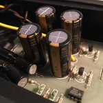
I'm currently renovating an humble Cabre AS45 active crossover.
I couldn't find any schematics for it so I work based on what I can see (am no electronic engineer..) - but it's a simple two way, 12dB/oct crossover.
I've already changed input and output coupling caps with back to back Elna Silmic II and recapped the rest with Nichicon KZ.
I've order a few OPA2134 to replace the TL082 at the outputs.
There's one single TL082 close to the inputs, I suspect it's an impedance buffer circuit.
Do I really need this impedance buffer at the input? What would happen if I would just bypass it? sorry if it is a very dumb question.
Let's say I keep it, can I just replace it with another OPA2134? (I'm aware of the importance of local decoupling, I've already swapped NE5532 for LM4562 in my Revox CD player and had to try different configurations)
thanks!
Attachments
Be careful when replacing all of these opamps, OPA213x do require a good bit more current than TL082 and this stuff adds up. You could end up with the supply running out of regulation, and some changes in the power supply may be needed.
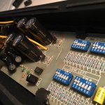
If you want to know what the opamp in question does, you best take some sharp high-resolution photos of both the top and the bottom side of the board and post those.
If you want to know what the opamp in question does, you best take some sharp high-resolution photos of both the top and the bottom side of the board and post those.
Be careful when replacing all of these opamps, OPA213x do require a good bit more current than TL082 and this stuff adds up. You could end up with the supply running out of regulation, and some changes in the power supply may be needed.
If you want to know what the opamp in question does, you best take some sharp high-resolution photos of both the top and the bottom side of the board and post those.
Yup, I know I didn't take the right picture, these were originally taken yesterday for a different purpose.
There's 5 opamps in total, i thought pSU problems might occur in, say, a professional mixing table using a ton of opamps on each channel, but not s simple device using 5 of them - but again I'm no electronic engineer so...
... how will I know if I run into problems? what would the symptoms be?
It all depends on how generously the power supply is designed, really. A small transformer, smallish capacitors and significant dropper resistors may spell trouble, not to mention power dissipation of those small regulator transistors (at least that's what I assume those TO-92s are).
You could simulate the extra load by adding one or multiple resistors across the supplies. R = (V+ - V-) / 5*(8-2.8) mA. For +/-15 V, that would be 1.15 kOhms (1 W, better 2 W) nominal. Should you be running short on higher-power resistors, you could try 6x 6.8k 1/4 W in parallel, otherwise 2x 2.2k 1 W will also do.
You could simulate the extra load by adding one or multiple resistors across the supplies. R = (V+ - V-) / 5*(8-2.8) mA. For +/-15 V, that would be 1.15 kOhms (1 W, better 2 W) nominal. Should you be running short on higher-power resistors, you could try 6x 6.8k 1/4 W in parallel, otherwise 2x 2.2k 1 W will also do.
Hmm..
looks like the TO92 are LM317
100mA...
there's two of those, one for each channel, so each one of them sees two and a half double opamps. Idle current of OPA2134 is 5mA (right?), but what about peak current?
power transformer is nothing special (well I wouldn't expect to see anything bigger in a line-level signal treatment device, except a high-end preamp or DAC) I'm not gifted enough to guess its specs just by the looks of it;
main filter caps are 4 x 470uF wich isn't much (even tho in Nichicon KZ size they take up all existing space)
I don't know what to make of all this.
What would worse case scenario be? Distortion? overheating of the voltage regs? Big boom or just bad sound? I mean, I can always put the old opamps (or something similar. TL072?) in there if OPA2134 doesn't work.
Do I really need this impedance buffer at the input? What would happen if I would just bypass it? sorry if it is a very dumb question.
If the signal source / previous unit has a beefy low-impedance output stage, you may be fine without the buffer. Otherwise, including the buffer is useful. If the source impedance becomes too high (similar to the impedances of the parts in the filter circuit), the signal source becomes part of the frequency dependent voltage dividers of the filter circuit; i.e. the signal source would act like a part of the filter circuit. The resulting filter transfer might be different from what was intended.
ah yes. "you could end up with the supply running out of regulation", you said it; that means a chance of destroying everything that's post regulators?
No, the regulators will probably run hot and shut down, then cool and come back on, then run hot .... you get the picture ? That may send some unwanted signals out.
I presume that these two regulators are one LM317L for the positive supply and one LM337L for the negative. Max current for these are 100mA.
According to datasheets the TL082 runs at 2.5mA max per amp, i.e. 25mA total. The OPA2134 runs at 5mA max per amp for a total of 50mA. The problem now is the heat dissipated in the regulators.
Assuming a 15VAC tranny, and Vout from regulators, these will drop about 4 to 5V at 50mA resulting in 250mW in dissipation. With a thermal resistance of 180deg/W this will cause a temperature rise of 180*0.25 = 45C. Add the ambient temp, say 30C, and the regulatorchips will be at 75C.
A bit on the high side, but it should be OK. If you could find some small piece of alu or copper-foil to make a small heat-sink it would make it a bit more safe- temperature wize.
Now the tranny. It is probably one of those PCB mounted things. If you are lucky, it will state on the top or the side something like "15V 2VA (7-8)" and "15V 2VA(11-12)" . Now, the 15V - you guessed it - means 15V ac out. The 2VA reads 2 VoltAmpere means that you basically can calculate the mac current as 2/15 = 133mA. If the VA rating is higher than 1.8 , you should be on the safe side. The numbers in () identifies the pins.
If you can't find any markings, then take out your ruler, measure the darn thing and post it here - I think I can make an educated guess.
Stability: the TL082 has a slew rate of 16V/uSec and the OPA2134 20V/uSec. That is not too different that it should pose a problem. Without a 'scope, you can play it safe and add a capacitor (1uF to 2.2uF ceramic) accross the OPA, from lead 4 to 8.
Thanks for your long and clear answer.
I have installed the 5 opa2134 a few days ago and it sounds so much better there's no way back; the two regulators do get hot to the touch but even after playing music LOUD I can still leave my fingers on them. I'd say 75c is a good temperature estimate.
I will take photos of the tranny and post them. It is small, but it's not a pcb device, it's bolted on the bottom of the case, if that matter (I suppose pcb trannies are the smallest type?)
I will buy thermal paste and make some small heatsinks out of soda can aluminium. That's going to be fun ��
The current draw of an opamp is the datasheet figure for quiescent plus whatever you send to the output.
If you have very light loading and no capacitance to charge/discharge, then the output currents can be very small, leaving the quiescent current as the only significant load for the regulators.
But if you have some capacitance as a load and have lower load impedances, then these can become the dominant load that is passed back to the regulators.
A 10k load driven to 2Vac is only 0.3mVpk from alternate supply rails. Add on the same again for small parasitic capacitance and you have only added 0.6mApk to the quiescent load. Small beer.
But if you had a 2k load driven to 4Vac and significant capacitance, then you can easily have 3 to 4mApk to add to your quiescent values for each opamp.
If there is limited supply rail decoupling at each opamp, then much of those peak currents have to come from the low output impedance of the regulator.
Last edited:
- Status
- This old topic is closed. If you want to reopen this topic, contact a moderator using the "Report Post" button.
- Home
- Source & Line
- Analog Line Level
- Opamp buffer @ active crossover input?